
User manual

RF Technology WinTekHelp User Manual Page 30
3.3.1 Parameter Programming for the Exciter WinTek Help User Manual
Note that “program” files can have both parameter and channel data in them. If one edits the parameter data, it
can be appended to an existing channel data program file by using the Append option.
Note also that when data is written to the flash database of the exciter or receiver, all the channel and parameter
data has to be erased, and then rewritten. When the user clicks on the “Save the Data to Flash Memory” button,
WinTekHelp will read the channel data, then it will erase the flash database, and then it writes the original
channel data, and the new parameter data to the flash database. At the end, WinTekHelp will force the firmware
to reset, so that the new parameters can take effect.
In the case that the “Edit/Examine Parameter Data” button is selected, and there is no receiver, nor exciter
connected to the unit, and no channel data file has yet been read, the user is prompted as to whether they wish to
edit receiver channel data or exciter channel data.
3.3.1 Parameter Programming for the Exciter
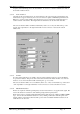
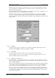
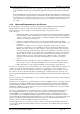
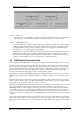
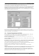
If, from the dialog box shown in Fig 17, the user selected the button “Edit/Examine Parameter”, a dialog box
such as that shown in Fig 18 would be shown, if the PC was connected to an exciter.
To set all the existing parameter data on an exciter to their factory default values, one can click on the “Set
Parameters to their Defaults” button.
Note that the MODEL and SERIALNO parameters cannot be erased or overwritten. These can only be set in the
initial factory calibration.
The “Channel Select Override” parameter allows the user to override any channel selection from the rear panel.
If this parameter is any value from 0 to 255, then the rear panel channel selection is ignored and this parameter
value is used instead. This feature saves the need to manually set jumpers on the rear panel.
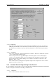
Line1 and Line 2 can be left as high impedance inputs, or be terminated in 600 ohms (the default). The “Line 1
Termination” and Line 2 Termination” fields can be used to set these parameters.
The External Tone input can be disabled, or enabled. The “External Tone Input” box selects which is
appropriate.
The External Tone Input can be used as a third audio input. Normally the External Tone Input is passed through
a 300Hz Low Pass Filter, but the next check box “Tone Low Pass Filter Bypass” can remove this filter.
Normally the Exciter accepts LOOP current passed in either direction through the Line 1 input pair (ie the
current is sourced externally). If the “Generate LOOP” box is set to “On”, then +12V is applied to the pair so
that LOOP current can be “sunk” rather than sourced through the Line1 inputs.
Fig 18