
User manual

RF Technology WinTekHelp User Manual Page 26
Advanced Programming for Receiver WinTekHelp User Manual
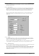
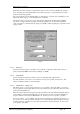
By clicking at the top or the bottom of the “Spin button” to the right of this field, one can step up or down
to the next RS470 “standard” tone. The field will display the tone value selected (in Hertz) and its EIA
code.
If the DCS Enable button is selected first, the user can enter the three digit octal DCS code that they wish
to have present before opening the Squelch. Note that the code entered is assumed to be not inverted. If
the exciter that one is connected to “inverts” the code, ie “1”s are transmitted as negative frequency shifts
of the carrier, then one should enter the logical inversion of the code required, eg the octal inversion of
357, is 420.
3.2.4 Advanced Programming for the Receiver
If, from the dialog box shown in Fig 11, the user selected the button “Edit/Examine Channel Data with
Advanced features, a dialog box such as that shown in Fig 15 or Fig 16 would be shown.
This new range of receivers is capable of several advanced features, not previously possible.
Some of these are:
1. Scanning: The ability to scan several frequencies; tuning into the first that has sufficient SINAD or
Carrier Strength etc. Then, if this frequency is deemed to be a non-priority frequency, hopping to a
“priority” frequency every so many seconds to see if that has sufficient Carrier strength or SINAD,
and, if it does, switching to that frequency.
2. COS/Loop Control: The ability to assert COS or Loop independently of each other. Which
frequency or CTCSS tone, or DCS code is received can then control whether COS, LOOP, or both,
are asserted.
In this way, for example, a receiver, in a repeater configuration, might “scan” two separate
frequencies, asserting COS on one, and LOOP on the other. Its COS output could be tied to the
PTT pin of an exciter, and its Loop output, would be connected to the exciter as part of the audio
connection between the exciter and receiver. If the exciter’s PTT input is asserted, the exciter can
be programmed to transmit on one frequency, but, if its LOOP input is asserted, it can transmit on
another. Thus the exciter’s carrier frequency becomes a function of which frequency is received.
In the same manner, a receiver, could select between two different exciters, or two different
frequencies on the same exciter, depending on which CTCSS tone, or DCS code was being
received.
3. Multi Tone Operation: The ability to accept several CTCSS tones as tone squelch values for the
same frequency, ie if any of the nominated CTCSS tones are present, then the Squelch will open.
4. Delays: The ability to specify start-up and tail delays for the generation of COS and Loop.
In order to avoid confusion we use a new term called a “slot”. In the world of Trunked Radio Systems, the word
“channel” is very closely aligned with the word “frequency”. It is confusing to refer to “channels” when,
because of the ability to scan, each “channel”, may have up to eight frequencies associated with it. To avoid
this confusion, we refer to the index that defines a particular group of scanning frequencies, as being a “slot”.
Where in the Basic Programming menu, there were up to 256 channels, in the advanced menu we can have up to
256 “slots”.
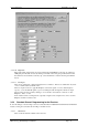
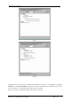
In order to program a “slot”, WinTekHelp uses a “tree” structure, and Figs 15 and 16 show a couple of different
examples of this structure.
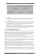
Fig 15 shows a “slot” that has been programmed with one frequency, 40MHz, (ie there is no scanning), but with
two CTCSS tones, 107.2Hz and 220Hz. It shows that the audio signal will be passed through a De-Emphasis
circuit, and that if the CTCSS tone of 107.Hz is received, that COS will be generated. If, on the other hand a
CTCSS tone of 220Hz is received, it will generate Loop but not COS. If no CTCSS tone, or any other CTCSS
tone is received, the Squelch will not open.
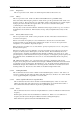
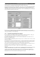
Fig 16 shows a channel that has been programmed to support scanning. The Priority Time Out parameter is
zero, which implies that there is no “priority” channel. As such, the receiver will try the first frequency
(48.00125MHz) to see if it has sufficient Carrier level and SINAD, and if not, it will attempt to tune to the
second frequency of 48.89875MHz. It will keep trying these two frequencies in turn until either is detected,
upon which it will stay tuned until the signal strength gets too low, and/or the noise too high, when it will resume
scanning. Note that the Carrier Squelch Offset for the first frequency is -3dB. This implies that the first
frequency can have a carrier level 3dB lower than the second frequency.
Note that in Fig 16, the “focus”, the cursor position if you like, is on the Carrier Squelch Offset value for the
second frequency (0dB). Notice that with the focus in this position there are text fields at the bottom of Fig 16
as against Fig 15.