
User manual

RF Technology WinTekHelp User Manual Page 20
3.2.1 Standard Channel Programming for the Exciter WinTekHelp User Manual
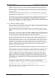
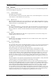
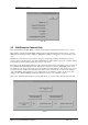
can be written to the receiver’s or exciters Flash memory, or it can be written to a file, or it can be appended to
an existing file. These three options are selected from the bottom three buttons of the dialog box shown in Fig
13.
Note that “program” files can have both parameter and channel data in them. If one edits channel data, it can be
appended to an existing parameter program file by using the Append option.
Note also that when data is written to the exciter’s or receiver’s Flash memory, the entire channel and parameter
database, in Flash memory, has to be erased and then rewritten. When the user clicks on the “Save the Data to
Flash Memory” button, WinTekHelp reads the device’s existing parameter data, then erases the entire Flash
database, and then writes the original parameter data, plus the new channel data back to the Flash database. At
the end, WinTekHelp forces the firmware to do a partial reset, so that the new channel data can take effect.
There are two buttons that the user can use to edit and/or modify the receiver’s or exciter’s channel data. Each
has a basic menu and an advanced menu. This new series of receivers and exciters has many advanced features
not supported by previous generations of Eclipse receivers and exciters. Those users, who do not wish to use
some of these advanced features, such as alternate channels (exciter), or scanning (receiver), should select the
button marked “Edit/Examine Channel Data with Standard features”. Where these more advanced features are
required, though, users should select the button marked “Edit/Examine Channel Data with Advanced features”
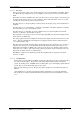
In the case that either of the previous two buttons are selected, and there is no receiver, nor exciter connected to
the unit, and no channel data file has yet been read, the user will be prompted as to whether they wish to edit
and/or examine receiver channel data or exciter channel data.
3.2.1 Standard Channel Programming for the Exciter
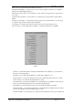
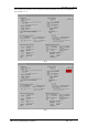
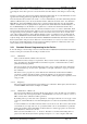
If, from the dialog box shown in Fig 11, the user selected the button “Edit/Examine Channel Data with Standard
features, a dialog box such as that shown in Fig 12 would be shown.
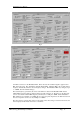
.3.2.1.1 Channel No
There can be 256 channels, numbered from 0 to 255.
Each channel can have a unique set of parameters. Thus, an exciter can have 256 different operating
states, depending upon the channel number read from the rear panel, or, what channel select override
parameter has been programmed.
The user can directly enter the channel number they wish to edit or examine in this field. Alternatively,
they can click at the top or bottom of the “Spin Button” to the right of this field, to step up or down the
list of channels.
This allows a user to program every exciter with the same channel data, and then direct installation
personnel to configure each unit, by simply selecting the channel to use in each site and rackframe
position. In this way, a failed unit can be swapped out quickly, without requiring any complicated on-site
setup procedure.
.3.2.1.2 Frequency
The user enters the frequency that the exciter will key up to in this field. This frequency must be between
25.0 and 50.0MHz, and it must be a multiple of 1.25kHz.
.3.2.1.3 CTCSS Tone or DCS code
The user enters the CTCSS tone frequency that the exciter wishes to add to the audio, before modulation.
They can enter in the tone frequency in Hertz, or the EIA RS470 code. If no tone is entered, or a tone of
0Hz is entered, then no CTCSS tone will be generated.
By clicking at the top or the bottom of the “Spin button” to the right of this field, one can step up or down
to the next “standard” RS470 tone. The field will display the tone value selected (in Hertz) and its EIA
code.
As well as CTCSS tones, from Rev 4 hardware, DCS codes can also be sent. These can be entered in the
conventional way as 3 digit octal codes. To specify that a DCS code is to be transmitted on a particular
channel, the checkbox called “DCS Enable” should be clicked on, and the appropriate code entered into
the “CTCSS Tone or DCS Code” edit box.
DCS codes can be transmitted “as is”, or “inverted”. The latter is convenient when dealing with a 3
rd
party receiver that effectively inverts the signal upon reception, ie “1”s cause a negative shift in the