
User manual

RF Technology WinTekHelp User Manual Page 18
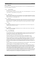
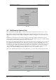
3.1.3.9 Audio State WinTekHelp User Manual
.3.1.2.9 Audio State
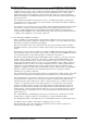
The “De-Emphasis or Flat freq. Response” field displays if the de-emphasis circuit has been switched in
or not. This field will display “DE-EMPHASIS” or “FLAT”.
The Input Peak Deviation field displays the level of the unfiltered received audio in terms of peak
deviation. After calibration, this value should be accurate to about 5% when the received signal strength
is greater than -110dBm and the deviation is at least 3kHz. This field can be used in setting up systems,
or in testing faulty units, by allowing the test technician to quickly check that the receiver is correctly
detecting signals from a signal generator or RF test set.
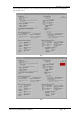
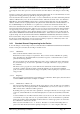
.3.1.2.10 Reference Oscillators and VCO sub-section
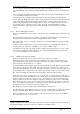
To understand this section a quick review of the Receiver’s RF circuit is necessary. A block diagram of
the receiver is shown in Fig 9.
Note that after band-pass filtering, the received signal is upconverted to a 1
st
IF frequency of
approximately 246MHz. Then it is downconverted to a 2
nd
IF frequency of exactly 21.4MHz, and then
down-converted again to the third IF frequency of 455kHz where it is de-modulated.
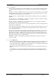
The “First IF VCO frequency” field shows the frequency of the first LO. The “Second IF VCO
Frequency” shows the frequency of the second LO. These two are related by the formula, F1 - F2 - Fr =
21.4MHz, where F1 is the first LO frequency, F2, the second LO frequency and Fr is the frequency being
received.
The VCO bias levels for the first and second LOs are displayed in the fields referred to as “First IF VCO
bias” and “Second IF VCO Bias” respectively.
As part of the receiver’s calibration, its reference oscillator is centred at 12.0MHz. This is done by
adjusting the bias over a varactor in the reference oscillator circuit. The adjustment is done by a DAC
output. The value that is written to the DAC is displayed, as a percentage of full scale, in the field
referred to as “Ref. Oscillator Adjustment.
The 21.85MHz LO is adjusted in the calibration procedure in the same manner as the reference oscillator.
The DAC value is also displayed as a percentage of full scale, in the field referred to as “Third LO
Adjustment”.
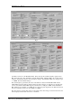
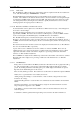
.3.1.2.11 ALARM Status
In Fig 8, there is a block marked “ALARM” just under the “OK” button near the top right of the dialog
box. This is missing in Fig 11. The presence of this field in Fig 9 indicates that there are Alarms
present. By clicking on the field a new Dialog Box opens, which displays which alarms are present.
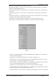
Fig 10 shows the Alarm Dialog Box for the receiver.
There are many alarm types shown. These alarms are described in more detail in the Operators Manual.
“Battery Low” is generated if the receiver battery level is low.
“Tuning Voltage Out of Range” is asserted if either, or both, of the bias voltages in the two VCO
circuits are out of range.
“Channel Not Programmed” is asserted if there is no channel data associated with the current channel
number.
“Frequency Out of Range” is asserted if the frequency assigned to the current channel is out of the
range of frequencies supported, ie 25 to 50MHz.
“Lock Failure” is asserted if either VCO is unable to achieve Lock when the Receiver tunes to the
selected frequency.
“Low RSSI” is an alarm generated if the signal being received is below the Carrier Alarm level.