
User manual

RF Technology WinTekHelp User Manual Page 17
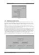
WinTekHelp User Manual 3.1.2.7 Received Frequency and Tone
The dc voltage across the front panel N.Sq potentiometer is read and then converted to an
approximateSINAD
1
value, and this approximate SINAD value is displayed in the Noise Squelch Level
field.
The receiver has a noise blanker circuit that can be disabled. If the circuit is enabled the button referred
to as “Noise Blanker On/Off” will be “ticked”.
Normally, the speaker is enabled whenever the Squelch is Open, and disabled when the Squelch is
Closed. If the Squelch Monitor switch, on the front panel is turned On, then the speaker will monitor the
audio, unless the Noise Detector has activated. In this manner, even if the Carrier Squelch, the tone
squelch, or the External Squelch have disabled the Line output, one is still able to listen to the audio on
the current frequency to which the receiver is tuned. The status of the Squelch Monitor switch is
displayed in this field. If the switch is On, the field will display “Closed”; otherwise, it will display
“Open”.
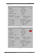
.3.1.2.7 Received Frequency and Tone
There are four fields in this section, which describe the state of the current RF signal to which the receiver
is tuned.
The actual frequency that the receiver is tuned to is displayed in the field referred to as “Frequency”. In
scanning mode, this value will be constantly changing whilst the unit is scanning.
The signal strength of the received signal is displayed in the field marked RSSI. It is displayed in dBm
and in microvolts.
An arbitrary signal strength indicator is shown in the field referred to as Signal Strength. This gives a
value from 0.0 to 5.0, where 0.0 is -120dBm or lower, and 5.0 is -80dBm or higher.
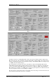
If a CTCSS tone is detected on the signal, its value is displayed in the field referred to as “Tone”. If the
tone frequency is within the standard tolerance of any of the standard EIA RS470 tones, the two-letter
code associated with that tone is also displayed.
.3.1.2.8 Output Level and Control Status
There are four fields in this section, which describe the state of the receiver outputs.
If the Squelch is Open, then any audio that is de-modulated from the Carrier is presented to the Line
output and the Direct Audio output, and, if enabled, COS and/or Loop will be generated. The Squelch
state is displayed in the field referred to as “Squelch”.
The Squelch Monitor will normally be Open only when the Squelch is opened. If the front panel switch is
in the “Closed” ie On position, then, it will open except when there is excessive noise on the received
signal. This field displays the current state of the audio switch that connects the demodulated audio to the
speaker amplifier. If it is Open, then no audio will be output from the speaker; if it is closed then it will.
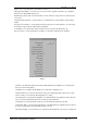
The “COS” field displays the current state of the COS output (defined by COS+ and COS-).
There are two basic modes of COS operation. In one mode, COS- is grounded, and COS+ will toggle
between 0V, and 12V (through a 680ohm resistor). In the other mode, it will toggle between shorting the
COS+ and COS- pins via an opto-coupler (“Looped”), or in having these two pins open circuit (“Open
Circuit”). In this second mode, the outputs are completely isolated from ground (or 12V). The Default
State of COS can be any of these four states, but its asserted state will be the opposite state for the same
mode. For example, if the default state is “Open Circuit”, then the asserted state will be “Looped”, or, if
the default state was “0V”, then the asserted state would be “12V”.
The default state of the COS output is defined in the Parameters Section (3.3.2).
The “Line O/P State” field displays the current state of the Loop output. The Loop output is the DC bias
applied to the LINE outputs. This bias can be 0V, or it can be +12V (through a 680 ohm resistor).
The Loop output has only two states, being 0V or 12V. The active state is the opposite of the Default
State defined in Section 3.1.1 (see also 3.3.2).
1
SINAD := (Signal + Noise + Distortion)/(Noise + Distortion). The value of SINAD shown in the field is based
on an assumption that the signal level component is a 1kHz tone with 3kHz deviation.