
User manual

RF Technology WinTekHelp User Manual Page 15
WinTekHelp User Manual 3.1.2 Receiver
3.1.2 Receiver
To understand some of the sub-sections of this Section it may be necessary to review the Block Diagram of the
receiver shown in Fig 23, in Appendix A.
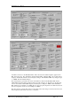
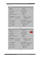
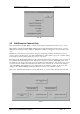
.3.1.2.1 Current Channel
This displays the current channel.
The current channel is a number from 0 to 255, which is used to select which frequencies or tones etc, the
receiver tunes to or scans when the receiver powers up.
.3.1.2.2 Battery Level
This is the voltage supplied to the receiver. It should be 28 +/- 0.5V. If this voltage falls below the Low
Battery Alarm Level, a low battery alarm will be generated. The Low Battery Alarm Level is a parameter
defined in Section 3.3.2, and it defaults to 24V.
.3.1.2.3 Firm. Rev.
This is the “Firmware Revision”. It has three fields. The first is the firmware revision itself expressed as
three numbers, in the form GG.RR.rr. These three numbers are referred to as the firmware’s Generation,
Release, and Revision. After this, the field contains the time and date when the firmware was actually
compiled.
.3.1.2.4 Model.
This field contains the Model name. This name is assigned at the factory, and cannot be changed, and
identifies what type of Receiver you have.
.3.1.2.5 Serial No.
Each Receiver is given a unique serial number that is used to identify each unit. This is assigned at the
factory, and cannot be changed.
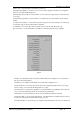
.3.1.2.6 Control Input Status.
This is a group of five fields.
The “Squelch In” button indicates if the External Squelch is asserted or not. If it is asserted, then the Line
Out, COS, and Loop signals are negated. Whilst the External Squelch will affect the COS, Loop and
Audio outputs, it does not affect the any scanning operation.
The Carrier Squelch Level is adjusted by the C.Sq Potentiometer on the Front Panel. As this
potentiometer is adjusted, the level seen in the Carrier Squelch Level field adjusts accordingly.
The Carrier Squelch Level is the Carrier level (in dBm) which must be exceeded before the receiver will
recognise a signal. If all other criteria associated with the signal (External squelch, noise, tones etc) are
met, then the receiver would open the squelch if the Carrier, of the signal to which it is tuned, exceeds
this level. In scanning mode, the receiver would stop scanning other frequencies, if it found that one of
the frequencies it was scanning had a signal strength higher than this level (assuming noise and tones etc
were OK).
The Noise Squelch Level is adjusted by the N.Sq Potentiometer on the Front Panel. As this potentiometer
is adjusted, the level seen in the Noise Squelch Level field adjusts accordingly.
The Noise Squelch level is an arbitrary adjustment. The noise detector measures the level of energy of
the audio above 3kHz, which reflects the noise present on the carrier (as the original transmitted audio
has all energy above 3kHz sharply filtered off). The level of that noise is peak detected, and is compared
with a voltage determined from the Front Panel N.Sq potentiometer. If the noise voltage exceeds this
threshold, defined by the Front Panel Potentiometer, then the receiver closes the Squelch, or keeps it
closed. If all other criteria associated with the signal (External squelch, Carrier Squelch, tones etc) were
met, then the receiver would open the squelch. In scanning mode, the receiver would stop scanning other
frequencies if it found that one of the frequencies it was scanning had a lower noise level than the level
defined by the N.Sq potentiometer, (assuming Carrier Squelch and tones etc were OK).