
User manual

RF Technology WinTekHelp User Manual Page 12
3.1.1.11 PA Status WinTekHelp User Manual
.3.1.1.11 PA Status
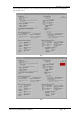
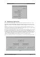
There are twelve fields in this section, which describe the state of the external Power Amplifier. If there
is no RF Technology’s Eclipse50 series power amplifiers connected to the exciter, these fields will be
blank.
The Eclipse series Power Amplifiers have their own A/D converter on-board, and the exciter interrogates
the data from this A/D converter via a 3-wire digital bus. Most of the fields in this section are a result
ofreading the various analogue values from the converter.
The field referred to as “Frequency Range” indicates what is the frequency range of the attached Power
Amplifier.
The field referred to as “Serial Number” contains the serial number of the Power Amplifier sent with the
exciter (assuming one was ordered with the exciter).
The field referred to as “Fwd Pwr” shows the actual Forward power of the Amplifier, and the field
referred to as “Rev Pwr” shows the Reverse Power.
The temperature of one of the two series connected output stage FETs is monitored and displayed in the
field referred to as “FET Temp”.
The voltage applied to the Power Amplifier is measured and is displayed in the field referred to as “Bat.
Level”. There is an alarm limit, for the Battery Level supplied to the PA, which is defined in Section
3.1.1, which defaults to 26V.
The drain currents for the Pre-Amplifier Stage and the Output Stage have small offset errors associated
with them. The offsets are not very significant, affecting the measured currents by less than +/-13%.
When the Power Amplifier is calibrated, the exciter stores the offset errors, which are displayed in the
fields referred to as “Offset”. This value is always subtracted from the measured values before they are
displayed in the fields referred to as “Drain Current”.
The FET bias voltages for the Output Stage and the Pre-Amplifier Stage are displayed in the fields
referred to as “Bias”.
.3.1.1.12 ALARM Status
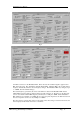
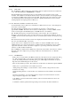
In Fig 6, there is a block marked “ALARM” just under the “OK” button near the top right of the dialog
box. This is missing in Fig 5. The presence of this field in Fig 6 indicates that there are Alarms
present. By clicking on the “ALARM” field a new Dialog Box opens, which displays which alarms are
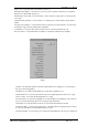
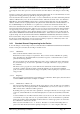
present. Fig 7 shows the Alarm Dialog Box for the exciter.
There are many alarm types shown. Most of these alarms, though, are as described in the Operators
Manual.
“Transmit Timeout” is an alarm generated if the unit has transmitted for more than the maximum
timeout allowed, as defined by the Transmit Timeout parameter (See the Exciter Parameters section –
3.3.1).