
User manual

RF Technology WinTekHelp User Manual Page 11
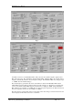
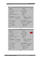
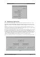
WinTekHelp User Manual 3.1.1.10 Reference Oscillators & VCO’s
The gain, that is defined by the Line Potentiometer and the firmware, is applied to the Voltage Controlled
Amplifiers (VCAs) on Line 1, Line 2, and the Tone Deviation (digital) Pot if the External Tone Input is
enabled. The current settings of the two VCAs are shown in the fields referred to as “Line 1 VCA
Adjustment” and Line 2 VCA Adjustment”. This shows the gain setting as a percentage of full scale.
With a nominal input level of 0dBm and with the Line Level Pot centred, these values should normally be
in the range 21-25%.
The actual audio signal that is injected into Line 1, Line 2, or the Microphone input, is detected at the
point where these are “mixed”, but before the deviation limiter. This signal level is displayed in dBm in
the field referred to as “Audio Level”.
The modulator is a conventional “two-point” modulator. This means that the modulation signal is applied
to the reference oscillator as well as the modulation VCO. The modulation signal is passed to the
reference oscillator straight from the deviation limiter, but the VCO modulation is passed through a
Voltage Controlled Amplifier (VCA). The adjustment range of this VCA is shown in the field referred to
as “Balance VCA Adjustment” as a percentage of full scale.
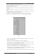
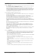
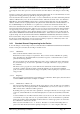
.3.1.1.10 Reference Oscillators and VCOs
Please consult Fig 5 for an understanding of how the Exciter synthesiser works. Note how there are two
phased locked loop frequency synthesisers, which are mixed together to produce the difference frequency.
That difference frequency is then filtered and amplified.
There are twelve fields in this section which describe the state of the two Phase Locked Loops (PLL).
Each Phase Locked Loop has a reference oscillator, a phase detector, and a Voltage Controlled Oscillator
(VCO).
The frequency of the two reference oscillators is nominally 12.0MHz. When the units are calibrated, the
firmware adjusts each reference frequency, using a varactor, to make both exactly 12.0MHz. This value is
saved, and is then used to set the reference frequency, each time the exciter turns on.
The firmware will automatically adjust the Channel PLL reference oscillator, if, at any time, an external
reference clock is connected to the exciter. The reference oscillator of the Modulation PLL is always
tracked to the Channel PLL reference oscillator. The adjustment of these two reference oscillators is
performed by three Digital to Analogue converters, one for the Channel reference oscillator, and two for
the Modulation reference oscillator. One of the two Modulation reference oscillator adjustment DAC
outputs is for very fine adjustment of the reference oscillator, and the other is for (relatively) coarse
adjustment (+/-20ppm). The DAC values for the Channel reference oscillator and the coarse Modulation
Reference oscillator adjustment are represented in the fields referred to as “Reference Oscillator
Adjustment” as a percentage of full scale.
If an external reference is detected, the button referred to as “Ext. Reference” will be “ticked”. The actual
frequency of the external reference will be displayed in the field referred to as “Ext. Ref. Frequency”.
The System Frequency is the frequency of the microprocessor itself. The firmware compares the phase of
the external reference, and the two on-board reference oscillators to the phase of the CPU clock. By
subtracting any pair of phase differences, it is able to compare the phase of any oscillator to any other
oscillator. To compute the accuracy of the actual frequencies to a very high order, it must scale the
frequencies calculated with the exact value of the System Frequency. During calibration, the System
Frequency is measured and stored and the exciter displays this stored value in the field referred to as
“CPU Clock rate”. The stored value is displayed with “grey” text. If an external reference is connected,
the System Frequency is recalculated every 2 seconds, and is displayed in this same field, but in dark
(high contrast) text.
The “Channel Ref Error” field will display any frequency error between an external reference and the
channel reference oscillator. If there is no external reference connected, this field is blank.
The “Modulation Ref Error” field displays the error of the Modulation reference oscillator with respect to
the Channel reference oscillator. This field is re-calculated every two seconds.
The last field in this section is the temperature of the Channel reference oscillator crystal. This is
displayed in the field referred to as “Xtal Temp”.