
Operating instructions


8
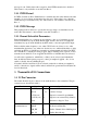
SPARE_SEL 5 Spare Select (for future use)
600Ω/HiZ Line
Line1+
Line1-
8
19
Transformer Isolated Balanced 0dBm
Input
600Ω/HiZ Line
Line2+
Line2-
10
22
Transformer Isolated Balanced 0dBm
Input
Direct PTT input 11 Ground to key PTT
T/R Relay driver
output
23 Open collector, 250mA /12V
Sub-Audible Tone
Input
Tone+
Tone-
9
21
>10kΩ, dc coupled
Table 3: Pin connections and explanations for the main 25-pin, D connector.
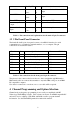
3.2 9 Pin Front Panel Connector
The female D-shell, 9 pin, front panel connector is an RS232 interface for serial
communications to a terminal, a terminal emulator, or to a computer. The pin
connections are described in table 4.
Function Pins Specification Pin name on IBM PC
TXD 2
Transmit Data (Output)
RxD
RXD 3 Receive Data (Input) TxD
RTS 8 Request To Send (Output) CTS
CTS 7 Clear To Send (Input) RTS
DTR 6 Data Terminal Ready(Output) DSR
DSR 1 Data Set Ready (Input) DCD
GND 5 GND GND
Table 4: Pin connections for the front panel 9 pin D connector.
The pinout for the connector has been chosen so that a straight-through BD9 male to
DB9 female cable can connect the transmitter to any male DB9 serial port on an IBM
PC compatible computer.
Note that for connection to a modem, a
cross-over cable will be required.
4
Channel Programming and Option Selection
Channel and tone frequency programming is most easily accomplished with RF
Technology WinTekHelp software. This software can be run on an IBM compatible PC
and can be used to calibrate a T50, R50, and PA50 as well as program channel
information. See the
WinTekHelp manual for further information.