
Operating instructions


7
message is sent. If this timer value is negative, then CWID transmission is disabled.
This feature is only available on models from Rev. 4.
2.11 CWID Period
If CWID (Continuous Wave Identification) is enabled, then this value indicates the time
in tenths of a second from one transmission to the next. If the value is zero, then the
CWID message is transmitted only once. This feature is only available on models from
Rev. 4.
2.12 CWID Message
This parameter allows the user to specify the message string to be transmitted as the
station ID. This feature is only available on models from Rev. 4.
2.13 Channel Selectable Parameters
Each channel defines two complete set of parameters. One set of parameters is used
when a transmitter keys up from the PTT-in input, and the other set is used when the
transmitter keys up from the LOOP-in, the PTT switch, or the microphone PTT input.
Each set defines what frequency to use, what CTCSS sub-tone (if any) to use, what
maximum line deviation to use, what tone deviation to use, what transmit delay (a delay
applied from PTT-in or LOOP-in to transmission), what transmit tail (delay from PTT-
in, or LOOP-in, to transmission being stopped, and No-TONE period (a period of extra
transmission in which No Tone is applied after PTT-in or LOOP-in has been released.
As well as these parameters, which Line (or Lines) can be selected, and whether the
lines should have flat frequency response or have pre-emphasis applied. Also, it can
enable or disable, the extra 20dB gain pad.
Note that both Line1 and Line 2 can be selected (each with or without pre-emphasis),
and if so, then the two signals will be mixed, and the Line potentiometer will adjust the
level of them both.
3 Transmitter I/O Connections
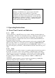
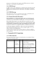
3.1 25 Pin Connector
The female D-shell, 25 pin, connector is the main interface to the transmitter. The pin
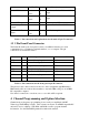
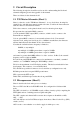
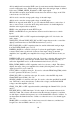
connections are described in table 3.
Function Signal Pins Specification
dc power +28Vdc(in)
0 Vdc
+5Vdc(out)
+12Vdc(out)
Vref
13, 25
1, 14
17
15
4
+24 to 32 Vdc
Common Voltage
Output for external Logic(100mA)
Output for an external relay(120mA)
Reference voltage for Tests
Serial
Communications
SCLK
MOSI
CH_EN
PA_CS
12
6
18
24
Serial Clock
Bi-directional Data Pin
Enables Channel Select Shift Register
Enables PA A/D chip