
Operating instructions


6
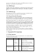
2.2 LINE Terminations
There are two main audio inputs, plus a direct audio (TONE) input. The direct audio
input is a High Impedance Balanced DC input, but the two audio inputs are AC coupled
(> 10Hz) inputs which can be High Impedance(HiZ), or 600 ohm inputs. Each input
can be software selected to be HiZ, or 600 ohms.
2.3 Exciter Low Battery Level
This is factory set to 24.0V, and defines the level of the DC supply that will cause an
Exciter dc supply low alarm.
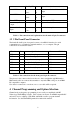
2.4 External PA Parameters
There are several user definable parameters associated with the external PA provided
with each exciter.
These are the PA low battery alarm level (default is 26V), the PA Set Forward Power
Level (defaults to 100W), the Forward Power Low Alarm Level (defaults to 90%), and
the Reverse Power Alarm Level (defaults to 25% - corresponding to a VSWR of 3:1).
2.5 Generate LOOP
Normally the transmitter will key up if dc current is sensed flowing in either direction
between Line1+ and Line1- (>=1mA). If the LOOP_VOLTS option is set to its non-
default setting, then a 12Vdc supply is applied to the pair through 660 ohms of source
impedance. (It would be expected, normally, that if this option is selected, then the
option to remove the 600 terminator from Line1, would also be selected). If dc current
flows from having applied this potential, then the transmitter will key up.
2.6 External TONE Input
Normally any signal applied to the TONE+/TONE- pair is ignored. If this option is
selected, then a Direct Audio input will be mixed with any audio received on either of
the other two lines, and with any CTCSS tones, or DCS codes being generated.
2.7 External Tone High Pass Filter Bypass
Normally the Direct
Audio, and the CTCSS/DCS outputs are passed through a 250Hz,
low pass filter. This filter can be bypassed by selecting this option.
2.8 Transmit Time
This parameter defines a maximum time limit for continuous transmission. It is
expressed in seconds and can be arbitrarily large (months in fact). If it is set to zero
seconds, then the transmitter can stay keyed up permanently.
2.9 Channel Select Override
This parameter allows the user to override the channel number that is read in via
connector P3. Normally it is
InActive, but if it is set to a value from 0 to 255, then the
exciter will behave as though that channel was hard-wired at the rear.
2.10 CWID Start Delay
If CWID (Continuous Wave Identification) is enabled, then this value indicates the time
in tenths of a second, from keying up an exciter to when the first station identication