
Operating instructions


14
isolation, and R446, and R448 set the level to be approximately 30% of maximum
deviation.
The output of U407B is passed (signal LINE_INP) to the Line Level Sense circuitry
(sheet 3) so that the CPU can determine the input line level.
U407B’s output is also passed to the limiter defined by D402, and D401. Resistors
R442, and R444 are used to “soften” the clipping, i.e. to “round off” the edges as the
voltage hits the clipping levels. This reduces the level of the lower order harmonics
produced.
U407C then buffers the output for mixing with the tone output circuitry.
The PWR_CNTRL_RAW DAC output is used to control the bias to the on-board RF
amplifier (see Sheet 8). The CPU output pin PWR_CNTRL_HIGH is effectively
summed with the DAC output to define three control ranges:
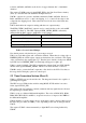
State of PWR_CNTRL_HIGH PWRCNTRL Voltage Range
TriState 2.98 – 5.86
Low (0V) 0.6 – 3.0
High (5V) 3.55 - 5.96
Table 9: Power Control Ranges.
Note that in practice only the first two power ranges are used.
U401 is an octal shift register and octal latch combined. When there is a rising edge on
LINEINP_DEN, the 8 shift register outputs are latched into the octal latch. The outputs
of the octal latch are the outputs Q0 to Q7. Thus the last 8 data bits clocked onto MOSI,
by SCLK, before LINEINP_DEN is clocked high, will appear on Q0 to Q7.
U406 is a quad 8 bit DAC. The CPU communicates with the DAC via SCLK, MOSI,
and the select signal LINEINP_ADSEL, which is low when the DAC is selected.
U302B is used to convert the DAC output into a bias level for the LCD. Note that, at
this stage, the LCD display option is not developed.
5.5 Tone Generation Section (Sheet 5)
U500 is a CTCSS tone encoder and decoder. The integrated circuit is also capable of
generating DCS signals.
The CPU accesses U500 via the serial bus using MOSI, SCLK, and the low active
Select signal CTCSS_SEL.
The output of the tone generator is mixed (summed) with any signals that are allowed
through analogue switch U301D.
U502 is set up as a balanced differential amplifier. The resistors R530, R531, R508,
R509, R510, R532, R533, and R511, are precision resistors to improve the CMRR of
the differential amplifier.
U502A amplifies, as well as mixes, the two audio inputs, and its output is either passed
through a low pass filter (at 250Hz), or not, depending on the state of analogue switch
U301A.
The output of U502C is then attenuated by a digital POT, before being buffered by
U502D.