
Operating instructions

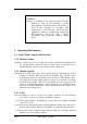

RF Technology R50 Page 5
if the other frequency is detected. Similarly, one
can enable/disable the default
assertion of COS and/or loop depending on which CTCSS tone is detected.
Other advanced features are:
a) de-emphasis: enabled or disabled, depending on frequency
b) start and end delays for COS and LOOP.
c) scanning interval for the priority frequency,
d) increments or decrements in the carrier level or noise level thresholds,
depending on the frequency. For example one frequency can be set to have a
higher noise threshold than another. Units are in dB of carrier signal, or
SINAD dB.
2.8 Standard Channel Parameters
Each channel can set the following standard parameters:
a) frequency,
b) one CTCSS tone, or DCS code.
3 Receiver I/O Connections
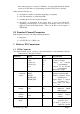
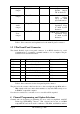
3.1 25 Pin Connector
The female D-shell, 25 pin, connector is the main interface to the transmitter. The pin
connections are described in Table 3.
Function Signal Pins Specification
DC Power +28Vdc(in)
0 Vdc
+5Vdc(out)
+12Vdc(out)
Vref
13, 25
1, 14
17
15
4
+15 to 32 Vdc
Common Voltage
Output for external
Logic(100mA)
Output for an external
relay(120mA)
Reference voltage
Serial
Communi
cations
SCLK
MOSI
CH_EN
SPARE_I/O1
SPARE_SEL
12
6
18
16
5
Serial Clock
Bi-directional Data Pin
Enables Channel Select
Shift Register
Spare Input or Output
(for future use)
Spare Select (for future
use)
600Ω Line
Output
Line+
Line-
8
19
Transformer Isolated
Balanced 600
Ω
0dBm Output
Carrier Operated
Switch
Output
COS+
COS-
10
22
Opto Coupled Transistor
Switch Output
(10mA)
External Squelch
Input
EXT_SQ 11
<1 VDC to force the
squelch to close.
>2 VDC or open ckt, to
enable the squelch