
Operating instructions


Page 6 RF Technology R50
to open
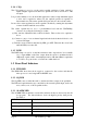
External Speaker
Output
EXT_SPK 24
AC Coupled External
Speaker Output,
5W @ 4Ω Load
Direct Audio
Output
DIR_AUD 21
>10kΩ
, AC Coupled
Audio Output
2Vp-p @ 3kHz
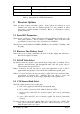
System Deviation
Discriminator
Audio
Output
DISC_AUD 20
>10kΩ
, AC Coupled
Un-
Squelched 2Vp-p
@ 3kHz System
Deviation
Sub-Audible
Tone
Output
SUBTONE
9
>10kΩ
, AC Coupled
Un-
Squelched, 2Vp-p
@ 3kHz System
Deviation
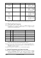
Table 3: Pin connections and explanations for the main 25-pin, D connector
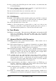
3.2 9 Pin Front Panel Connector
The female D-shell, 9 pin, front panel connector is an RS232 interface for serial
communications to a terminal, a terminal emulator, or to a computer. The pin
connections are described in table 4.
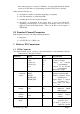
Function Pins Specification Pin name on IBM PC
TXD 2
Transmit Data (Output)
RxD
RXD 3 Receive Data (Input) TxD
RTS 8 Request To Send (Output) CTS
CTS 7 Clear To Send (Input) RTS
DTR 6 Data Terminal Ready(Output) DSR
DSR 1 Data Set Ready (Input) DCD
GND 5 GND GND
Table 4: Pin connections for the front panel 9 pin D connector
The pinout for the connector has been chosen so that a straight-through BD9 male to
DB9 female cable can connect the transmitter to any male DB9 serial port on
an IBM PC compatible computer.
Note that for connection to a modem, a
cross-over cable will be required.
4
Channel Programming and Option Selections
Channel and tone frequency programming are most easily accomplished with RF
Technology WinTekHelp software. This software can be run on an IBM
compatible PC and can be used to calibrate a T50, R50, and PA50 as well as