Eclipse Ser ies RF Technology rfinfo@rftechnology.com.
CONTENTS 1 CONTENTS OPERATING INSTRUCTIONS 1.1 FRONT PANEL CONTROLS AND INDICATORS 1.1.1 1.1.2 1.1.3 1.1.4 1.1.5 1.2 2 PWR LED SQ LED ALARM LED 2 2 2 RECEIVER OPTIONS 2.1 2.2 2.3 2.4 2.5 2.6 2.7 2.8 3 3.1 3.2 1 1 1 FRONT PANEL INDICATORS 1.2.1 1.2.2 1.2.3 2 Monitor Volume Monitor Squelch N.SQ 1 C.
7.2 7.3 PHYSICAL CONFIGURATION FRONT PANEL CONTROLS, INDICATORS, AND TEST POINTS 7.3.1 7.3.2 7.3.3 7.4 18 18 18 ELECTRICAL SPECIFICATIONS 7.4.1 7.4.2 7.4.3 7.4.4 7.4.5 7.4.6 7.4.7 7.4.8 7.4.9 7.4.10 7.4.11 7.4.12 7.4.13 7.4.14 7.4.15 7.4.16 7.4.17 7.4.18 7.4.19 7.4.20 7.4.21 7.4.22 7.4.23 7.4.24 7.4.25 7.
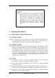
1 OP WARNING Changes or modifications not expressly approved by RF Technology could void your authority to operate this equipment. Specifications may vary from those given in this document in accordance with requirements of local authorities. RF Technology equipment is subject to continual improvement and RF Technology reserves the right to change performance and specification without further notice. 1 Operating Instr uctions 1.1 Fr ont Panel Contr ols and Indicator s 1.1.1 Monitor Volume The Mon.
1.1.4 C.SQ The C.SQ trimpot is used to set the carrier squelch sensitivity. Carrier squelch is useful at higher signal levels than noise squelch and can be used from 1 - 200 uV input. It is provided mainly for use in fixed link applications where a high minimum signal to noise ratio is required or where very fast squelch operation is required for data transmission. The carrier squelch will open and close in less than 2 mSec.
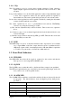
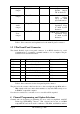
is out of range. 1 flash, pause Low dc supply voltage LED ON continuously External squelch is active Table 1: Interpretations of LED flash cadence 2 Receiver Options There are many software selectable options. Some options are selected on a per channel basis, and some are defined globally (i.e. the parameter is fixed irrespective of which channel is selected). Below is a description of these global parameters 2.1 Ser ial I/O Par ameter s There are two serial ports.
In states (c) and (d), the COS+/COS- pair can “sink” current, or not sink current, that is sourced elsewhere. The receivers will either toggle between states (a) and (b), or toggle between states (c) and (d), depending on the state of the squelch. The user can select which of these two modes they wish to use. The default COS mode is to toggle between states (a) and (b) 2.
if the other frequency is detected. Similarly, one can enable/disable the default assertion of COS and/or loop depending on which CTCSS tone is detected. Other advanced features are: a) de-emphasis: enabled or disabled, depending on frequency b) start and end delays for COS and LOOP. c) scanning interval for the priority frequency, d) increments or decrements in the carrier level or noise level thresholds, depending on the frequency.
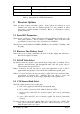
to open Coupled External Speaker Output, 5W @ 4Ω Load External Speaker Output EXT_SPK 24 AC Direct DIR_AUD 21 >10kΩ, AC Coupled Audio Output 2Vp-p @ 3kHz System Deviation Discriminator Audio Output DISC_AUD 20 >10kΩ, AC Coupled UnSquelched 2Vp-p @ 3kHz System Deviation Sub-Audible Tone Output SUBTONE 9 >10kΩ, AC Coupled UnSquelched, 2Vp-p @ 3kHz System Deviation Audio Output Table 3: Pin connections and explanations for the main 25-pin, D connector 3.
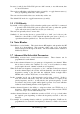
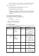
program channel information. See the WinTekHelp users manual for further information. 5 Circuit Descr iption The following descriptions should be read as an aid to understanding the block and schematic diagrams given in the appendix of this manual. There are 7 sheets in the schematic in all. 5.
FPSW1, FPSW2 and FPSW3 are three pins that have been reserved for future use as switch inputs. LOOP/VOLTS_SEL is a CPU output that when high applies 12V of dc feed to the audio output. LINE_LEVEL_U/D and LINE_LEVEL_INC are CPU outputs which are reserved for controlling a digital potentiometer in future. COS_VOLTS_ON/OFF is a CPU output that when high applies 12VDC feed to COS+ terminal, so that the COS can be selected as +12VDC source or a free switch.
TXD_TTL, RXD_TTL, RTS_TTL, CTS_TTL, DTR_TTL, DSR_TTL, are RS232 data pins which are connected to the main front panel serial port, after conversion to/from RS232 compatible voltage levels by U202 and U201. N_DET is used to sense the noise squelch output of the receiver section. (see) SUBTONE_IRQ is connected to the interrupt pin of the FX805 (U500).
U303A, U303D are buffers that isolate the bias voltage. The Microcontroller, U204, has both of these buffered voltages connected to two of it’s A/D ports. U304A, U304B divide the FoLD of the PLL chip by 100, and send it to a Timer input pin of the MicroController, U204. 5.4 Receiver Section (Sheet 4) The RF input signal (25MHz-50MHz) is first filtered with a band-pass filter.
components between FIL405 and U401 form the matching network for the filter. U401 is an IF receiver IC which includes mixer, oscillator, amplifiers and discriminator. It down-converts the 2nd IF to the 3rd IF at 455kHz, which is filtered by ceramic filters FIL402, and FIL403, before the signal is demodulated(discriminated). The discriminator uses ceramic resonator X401 as its 455kHz reference. X402 is a crystal used to create a 21.855MHz oscillator that becomes the 3rd LO.
the possibility of replacing MX401 with a mixer that requires a higher level of LO drive (but an improved IP3 figure). 5.6 Audio Pr ocessing Section (Sheet 6) The discriminator output from the RF section is connected, in this audio section, to a peak detector formed by U604 and C623. This peak detector output is passed to an A/D input of the Microcontroller to be used as a simple deviation meter. This raw detected audio is then attenuated by R642 and R655 before being filtered.
closes depends on the way in which the channel is programmed by the user. The position of RL602 is controlled by the signal LOOP/VOLTS_SEL from the MicroController. Opto-coupled transistor switch U601 provides a COS (Carrier Operated Switch) output which is controlled by the digital COS_POLARITY signal from the MicroController. The output COS+ and COS- can be used as +12V DC source or a free switch depending on the status of the relay RL601.
6 Field Alignment (Calibr ation) Procedure 6.1 Standar d Test Equipment Some, or all of the following equipment will be required: • Power supply set to 28Vdc, with current >0.25A. • RF Signal Generator with 50 Ohm Output impedance, and Frequency range 25-50MHz. The signal generator must be capable of generating a carrier aith output level adjustable from –60dBm to –128dBm. It must be able to FM modulate the carrier with a 1kHz audio signal with deviations of 3 and 5kHz.
Then it will ask the operator to enter the value of Vref (as measured at TP913, see 5.7). Measure the voltage, at TP913 (Vref) and type it on the command line... Unless the reference diode D911 has been replaced, this should not be done. The user should simply hit the Enter key to bypass this operation. If, though, D911 has been replaced for some reason, then, the lid of the unit should be removed, and the voltage measured. TP913 can be found just above JP12 (near the centre of the exciter).
is 388mV.(eqvt to 0dBm into 600 ohms) Enter < RET> when done. Set the RF signal generator's output to -60dBm Enter < RET> when done. rssi_scale is 0.417dBm/dac step, and rssi offset is -137.500dBm) Adjust the Modulation to only 1KHz max deviation Enter < RET> when done. deviation_scale is 1.000dBm/dac step, and deviation offset is .000dBm Adjust the Carrier Squelch to the desired level Enter < RET> when set. -99.
into any position, in any site, without the need to perform on-site reprogramming. This can be convenient in maintenance situations. The parameters that can be defined on a per channel basis are: • • • • • • • • The frequency, or if scanning is enabled, the list of frequencies to be scanned. If scanning is enabled, the selection of a priority frequency (if there is one), and how often it is checked. The CTCSS tone, or tones, expected on each frequency, or, DCS code expected on each frequency.
7.2 Physical Configur ation The receiver is designed to fit in a 19 inch rack mounted sub-frame. The installed height is 4 RU (178 mm) and the depth is 350 mm. The receiver is 63.5 mm or two Eclipse modules wide. 7.3 Fr ont Panel Contr ols, Indicator s, and Test Points 7.3.
7.4.4 Fr equency Stability ±5 ppm over 0 to +60 C, standard ±12 ppm over -30 to +60 C. 7.4.5 Number of Channels 256, numbered 00 - 255 7.4.6 RF Input Impedance 50 ohms. 7.4.7 IF Fr equencies 1st IF frequency 246MHz +/- 120kHz 2nd IF frequency 21.4MHZ 3rd IF frequency 455KHz 7.4.8 Sensitivity -119 dBm for 12dB SINAD -116 dBm for 20dB Quieting 7.4.9 Selectivity 80dB per RS204C 7.4.10 Spur ious and Image Rejection 90dB 7.4.11 Inter modulation 80dB 7.4.12 Modulation Acceptance BW 7.5KHz 7.4.
7.4.15 Receiver Frequency Spr ead Less than 1dB change in sensitivity over the band 7.4.16 Receiver Conducted Spur ious Emission Less than -67dBm from 1 to 3000MHz 7.4.17 Audio Fr equency Response (a) 600 Ohm Line and Direct Output: +1/-3 dB 300 - 3000 Hz relative to either a flat response or 750 uSec. deemphasis (b) Sub-Audio Output: +1/-3dB 67 - 250 Hz @ 3kHz deviation 7.4.18 Audio Output Level (a) 600 Ohm Line: Adjustable -10 to +10 dBm (b) Monitor Loudspeaker: 5 Watts with external speaker, 0.
7.4.21 Car r ier Oper ated Switch (COS) Output The carrier operated switch output is via an Opto-coupler. Collector and emitter connections are available to allow connection for source or sink. The Opto-coupler can be linked inside the receiver to be on when a carrier is detected or to be on in the absence of carrier. Internal connections are provided by a relay so that 12VDC can be connected to the 600 Ohm line for use over a single pair. 7.4.
The External Squelch Input can be connected to the T/R Relay pin on Eclipse transmitters mute the receiver during transmission. 7.5 Connector s 7.5.1 Antenna Connector Type N Female Mounted on the module rear panel 7.5.2 Power & I/O Connector 25 pin "D" Male Mounted on the rear panel 7.5.
APPENDIX A EIA CTCSS TONE FREQUENCIES Frequency No Tone 67.0 71.9 74.4 77.0 79.7 82.5 85.4 88.5 91.5 94.8 100.0 103.5 107.2 110.9 114.8 118.8 123.0 127.3 131.8 136.5 141.3 146.2 151.4 156.7 162.2 167.9 173.8 179.9 186.2 192.8 203.5 210.7 218.1 225.7 233.6 241.8 250.
R50 PARTS LIST B R50 Parts List Main PCB Assembly Parts Ref.
R50 PARTS LIST C322 C323 C324 C327 C328 C329 C330 C401 C402 C403 C404 C405 C406 C407 C408 C409 C410 C411 C412 C413 C415 C416 C417 C418 C419 C420 C421 C422 C423 C424 C425 C426 C427 C428 C429 C430 C431 C432 C433 C434 C435 C436 C437 C438 C439 C440 C441 C442 C443 C444 C445 C446 C448 Capacitor 18P+/-5% NPO 50V 0603 Capacitor 8P2+/-5% NPO 50V 0603 Capacitor 33P+/-5% NPO 50V 0603 Capacitor 1U5+/-10% 10V TANT 1206 Capacitor Electrolytic L ESR 16V 100U 7343 Capacitor 10N+/-5% NPO 50V 1206 Capacitor 100N+80/-20% Y5V
R50 PARTS LIST C449 C450 C451 C452 C453 C454 C455 C456 C457 C458 C459 C460 C461 C462 C463 C464 C466 C467 C468 C469 C470 C471 C473 C474 C475 C476 C477 C478 C479 C480 C481 C482 C483 C484 C486 C487 C488 C489 C491 C492 C493 C494 C495 C496 C501 C503 C502 C504 C505 C506 C507 C508 C509 Capacitor 8P2+/-0.25 NPO 50V 0603 Capacitor 2P7+/-0.
R50 PARTS LIST C511 C512 C513 C514 C515 C516 C518 C519 C520 C521 C522 C523 C524 C525 C526 C527 C528 C529 C530 C531 C532 C533 C534 C535 C536 C537 C538 C539 C541 C542 C543 C544 C545 C547 C548 C549 C550 C551 C552 C553 C554 C555 C556 C557 C558 C559 C560 C561 C563 C564 C601 C602 Capacitor 100N+80/-20% Y5V 25V 0603 Capacitor 100N+80/-20% Y5V 25V 0603 Capacitor 100N+80/-20% Y5V 25V 0603 Capacitor 100N+80/-20% Y5V 25V 0603 Capacitor 100N+80/-20% Y5V 25V 0603 Capacitor 100N+80/-20% Y5V 25V 0603 Capacitor 10N+/-10%
R50 PARTS LIST C604 Capacitor Electrolytic BIPOL 50V 22U+/-20% RB.2.4 C605 Capacitor 15U /6.3V A-CASE ELECTROLYTIC C606 Capacitor 1U+80/-20% Y5V 25V 1206 C607 Capacitor 47N+/-10% X7R 50V 1206 C609 Capacitor 15U /6.
R50 PARTS LIST C940 Capacitor Electrolytic 10U 16V 6032 C941 Capacitor Electrolytic 10U 16V 6032 C943 Capacitor Electrolytic 10U 16V 6032 D102 Diode LED Red RT ANG MTG D103 Diode LED Yellow RT ANG MTG D104 Diode LED Green RT ANG MTG D200 Diode Dual GP BAV99 SOT23 D301 Diode V Capacitor MMBV109 SOT23 D401 Diode Schotky BAT17 SOT23 D403 Diode Dual GP BAV99 SOT23 D404 Diode Dual GP BAV99 SOT23 D405 Diode Schotky BAT17 SOT23 D406 Diode V FilterCapacitor MMBV109 SOT23 D407 Diode Zen 5V1 BZX84C5V1 SOT23 D501 Diod
R50 PARTS LIST L410 Inductor 270NH+/-5% 0805 L411 Inductor 270NH+/-5% 0805 L412 Inductor 220NH+/-5% 0805 L413 Inductor 220NH+/-5% 0805 L414 Inductor 220NH+/-5% 0805 L417 Inductor 100NH+/-5% 0805 L419 Inductor 100NH+/-5% 0805 L420 Inductor 150NH+/-5% 0805 L421 Inductor 680NH+/-10% 1008 L422 Inductor 100NH+/-5% 0805 L423 Inductor 2U2H+/-5% 1008 L424 Inductor 2U2H+/-5% 1008 L425 Inductor 560NH+/-5% 0805 L426 Inductor 3U3H+/-10% 1008 L501 Inductor 18N5H+/-5% L502 Inductor 3U3H+/-10% 1008 L503 Inductor 3U3H+/-10
R50 PARTS LIST Q206 Q301 Q401 Q402 Q403 Q404 Q405 Q406 Q407 Q408 Q501 Q502 Q503 Q504 Q601 Q602 Q603 R103 R104 R201 R202 R203 R204 R205 R206 R207 R209 R210 R211 R212 R213 R217 R218 R219 R220 R221 R222 R223 R224 R225 R226 R228 R229 R230 R231 R232 R233 R234 R235 R236 R237 R238 R239 Transistor NPN GP SOT23 Transistor NPN GP SOT23 Transistor NPN RF BFQ17 SOT89 Transistor NPN RF BFQ193 SOT89 Transistor NPN RF BFQ17 SOT89 FET NJ MMBFJ309 SOT23 Transistor PNP RF BFR92A SOT23 Transistor PNP RF BFR92A SOT23 Transist
R50 PARTS LIST R240 R241 R242 R243 R244 R245 R301 R302 R303 R304 R305 R306 R307 R308 R309 R310 R311 R312 R313 R314 R315 R316 R317 R318 R319 R320 R321 R322 R323 R324 R325 R326 R327 R330 R331 R332 R333 R401 R402 R403 R404 R405 R406 R407 R408 R409 R410 R411 R412 R413 R414 R415 R416 Resistor 0805 10K+/-5% 1/8W Resistor 0805 22R+/-5% 1/8W Resistor 0805 47K+/-5% 1/8W Resistor 0805 220R+/-5% 1/8W Resistor 0805 10R+/-5% 1/8W Resistor 0805 12K+/-5% 1/8W Resistor 0805 22R+/-5% 1/8W Resistor 0805 10K+/-5% 1/8W Resist
R50 PARTS LIST R417 R418 R419 R420 R421 R422 R423 R424 R425 R426 R427 R428 R429 R430 R431 R432 R433 R434 R435 R436 R437 R438 R439 R441 R442 R443 R444 R445 R446 R448 R449 R450 R452 R453 R454 R455 R456 R457 R458 R459 R460 R461 R462 R463 R464 R465 R466 R467 R468 R469 R507 R508 R509 Resistor 0805 680R+/-5% 1/8W Resistor 0805 680R+/-5% 1/8W Resistor 0805 10K+/-5% 1/8W Resistor 0805 100K+/-5% 1/8W Resistor 0805 10K+/-5% 1/8W Resistor 0805 100K+/-5% 1/8W Resistor 0805 10K+/-5% 1/8W Resistor 0805 680R+/-5% 1/8W Re
R50 PARTS LIST R511 R512 R514 R515 R516 R517 R518 R519 R520 R521 R522 R523 R524 R526 R529 R530 R532 R533 R535 R538 R541 R542 R543 R544 R549 R601 R602 R603 R604 R605 R606 R607 R608 R609 R610 R611 R612 R613 R614 R615 R616 R617 R618 R619 R620 R621 R622 R623 R624 R625 Resistor 0805 1K+/-5% 1/8W Resistor 0805 10K+/-5% 1/8W Resistor 0805 10K+/-5% 1/8W Resistor 0805 100R+/-5% 1/8W Resistor 0805 100R+/-5% 1/8W Resistor 0805 100R+/-5% 1/8W Resistor 0805 100R+/-5% 1/8W Resistor 0805 100R+/-5% 1/8W Resistor 0805 100R
R50 PARTS LIST R628 Resistor 0805 15K+/-5% 1/8W R629 Resistor 0805 15K+/-5% 1/8W R630 Resistor 0805 75K+/-5% 1/8W R631 Resistor 0805 12K+/-5% 1/8W R632 Resistor 0805 470K+/-5% 1/8W R633 Resistor 0805 560R+/-5% 1/8W R634 Resistor 0805 10R+/-5% 1/8W R635 Resistor 0805 4K7+/-5% 1/8W R636 Resistor 0805 100K+/-5% 1/8W R637 Resistor 0805 1K+/-5% 1/8W R638 Resistor 0805 3K3+/-5% 1/8W R639 Resistor 0805 39R+/-5% 1/8W R640 Resistor 0805 220R+/-5% 1/8W R641 Resistor 0805 2R2+/-5% 1/8W R642 Resistor 0805 39K+/-5% 1/8W
R50 PARTS LIST U201 IC Quad CMOS RS232 RCV SO14 U202 IC Quad CMOS RS232 DRV SO14 U203 IC Reset Generator S08 U204 IC MCU 68HC12, TQFP112 U205 IC 3-8 Line Decoder SO16 U207 IC Flash 5V TSOP40 U208 IC SRAM 4M SOP-32 U301 IC Quad 8BIT DAC MAX534 SSO16 U302 IC Dual PLL 1.
A B C D 1 1 RS 232 SERIAL_BUS REF SET RF INPUT REF X402 2 2ND LO BIAS 1ST LO BIAS LINE LEVEL VIN CSQ NSQ RSSI ALARM SQ PWR DUAL PLL CHIP U302 3 A/D U204 3 4 1ST LO AMP FIL401 246MHz SAW FILTER 4 U202 U201 2ND LO AMP 2ND VCO Q502 MA504 MA506 NOISE BLK GATE Q404 BOULLE BAL.
A B C 1 DB25 J1 13 25 12 24 11 23 10 22 9 21 8 20 7 19 6 18 5 17 4 16 3 15 2 14 1 2 +5V Vref CH_EN +12V PTT_IN T/R_RELAY LINE2+ LINE2TONE+ TONELINEGPS+ GPSLINE+ +28V GND 180R R24 GND D14 GND 180R R25 180R R23 GND R26 3 MOSI SCLK PA_CS CS2 Q1 BSS138 BZX84C5V6 D13 180R BAV99 R22 180R R21 180R BAV99 5V_PROT D12 5V_PROT GND BAV99 D11 5V_PROT 180R 47K R1 D9 BAW56 47K R2 4 15 2 9 7 1 C1 100nF C C Q Q PL R19 22R I7 I6 I5 I4 I3 I2 I1 I0 SI U1 6 5 4 3 14 13 12
1 2 3 4 5 6 7 8 +5V 10K R601 2K7 Q601 MMBT3906 COS+ U601 2 D COS_POLARITY COS- K R603 3K3 Q602 BSS138 FLAT R610 0R 22R Q603 BSS138 SQ SQ LOOP/VOLTS_SEL 4K7 +5V R606 18K C601 1uF R624 1M VCC XTAL/CLK R637 1K 4 IRQ C605 R613 1uF 10K R621 33K 16 17 R623 330K BAV99 14 13 15 R614 10K ADDR +5V Din R650 20 19 21 C611 100nF R625 100K R626 100K RX_SUB_OUT R636 100K LM224 5 RX_IN+ RX_INRX_OUT 12K C619 GND LM224 R629 15K C606 1uF VR601 10K GND GND COM
1 2 1st_PLL_IN 3 4 R507 1st_PLL_IN 1K 5 C531 22pF R525 C532 10pF L503 GND D501 MMBV105G L501 A05T Q501 MMBFJ309 C533 4p7F C501 2p2F D GND GND C534 10pF +10V R515 100R R521 L504 220nH GND GND R516 +10V C522 120pF GND C525 10nF C504 10uF GND GND R536 C540 *10R *10nF 150R 270R C511 100nF L505 220nH C558 10uF MA501 VAM-6 C503 C512 10uF 100nF GND L507 220nH GND GND L508 *3u3H R547 *12K MA502 VAM-6 GND L514 27nH C552 330pF GND 1st_LO C551 GND C510 *100nF +10V
1 2 3 4 5 6 7 8 Receiver section RCV.
3 4 5 C429 100nF frontend filter Simulation file: c:\eagle\work\9LP&9HP.SCH C401 120pF C417 150pF C402 120pF C420 180pF L405 132-20SM L406 132-17SM L407 132-13SM RF_In RF_In RFin -119dBm L401 132-15SM L404 132-18SM L403 132-15SM C416 150pF C407 1nF 1st_LO C403 120pF L409 680nH 25MHz HIPASS FILTER & 50MHz LOWPASS FILTER Simulation file: c:\eagle\work\f2550amp.
1 2 3 4 5 6 7 8 +10V +10V EN 12V L902 C903 + 33uF + C938 3 6 D907 MBRM140T3 GND VIN C923 Vout Vout U911 LM317LM +10V 2 4 1 Vin C926 + C940 100uF 100nF GND Tantalum, ESR <= 0.3 ohms Tantalum, ESR <= 0.3 ohms +10V U910 LM1117-ADJ 3 33uH DS5022P-224 TP910 12V L901 1 Vout 12V 100nF R925 150R GND 5 10uF ADJ 5 470uF Tantalum, ESR <= 0.
R237 47K VIN_SENSE R202 GND 46 MMBT2369A C203 47 44 10K EXTAL Q204 R238 1K GND C226 C205 C204 C206 C207 100nF 100nF 100nF 100nF 100nF R225 10K XTAL U204 GND 74 71 70 69 PF6 PF3 PF2 PF1 LCD_RS LCD_R/W LCD_E MON_SQ LCD_RS LCD_R/W LCD_E +5D3 MON_SQ +5D1 R220 10K D R219 TP200 10K CS0 TP207 R/W +5D2 R/W 9 14C88 8 TXDATA 3 2 C U201A 4 CTS CTS ECLK SQ_LED U201B 6 5 C DBGRX 10 SCLK MOSI SCLK MOSI 14C89A 8 14C89A 9 C U201C 13 RXDATA U201D 11 12 C 3 DTR
1 2 3 4 5 TP100 MOSI RF Section RF.Sch TP101 SCLK RF_IN GND 1st_LO_BIAS 2nd_LO_BIAS N_BLK_EN RESET SQ_LED D SQ_LED D104 POWER RESET PWR_OK PWR_OK PLL_SEL RCV_ADSEL RCV_ADSEL SCLK MOSI SCLK MOSI N_DET DISC TP102 28V ALARM_LED N_BLK_EN PLL_SEL AGND R104 180R D103 SQ 1st_LO_BIAS 2nd_LO_BIAS GND ALARM_LED LCD_BIAS RESET R103 180R D102 ALARM PLL_SENSE Fo_PLL LCD_BIAS 8 +5D3 RSSI PLL_SENSE Fo_PLL RF_IN 7 MicroProcessor MCU.