
Operating instructions


RF Technology PA501 Page 20
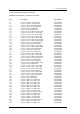
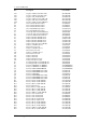
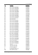
A ENGINEERING DIAGRAMS
point). Measure and record the supply current, which should be below 25A
(typically 21A). Measure and record the voltage drop across the collector current
sense resistors (R21, R52, R53). The calculated supply current to Q2 and Q3
should be within 1A of each other.
10. Measure the input RF (driving) power level. the forward power level should be
less than 14W. The reflected power level should be less than 1/5 of the forward
power. Measure and record the forward and reverse power voltages.
11. Continuing at the operating frequency (or 500MHz if not specified), connect the
directional power meter to the output of the DUT. Connect the output from the
directional power meter to a load providing an SWR of 2.0:1 (or -8dB return loss).
Observe the forward power from the DUT to the load. Adjust the REVPWR pot
(RV1) until the amplifier output just starts to reduce, and return the pot until the
output returns to the set level. Attach the “5dB return loss” load (SWR of 3.5:1),
and see that the amplifier output falls.
12. Replace the normal attenuator/load, and reconnect the power meter, or use the
directional power meter if preferred. Reduce the FWDPWR pot (RV2) to obtain
an output power of 2/3 the set level (nominally 80 Watts). Adjust the RFO pot to
just extinguish the front panel RFO LED, and then return it slightly until the LED
just comes back on. Reset the FWDPWR pot (RV2) to obtain the nominal 100
Watt output level.
13. Reconnect the spectrum analyser to the attenuating load, but continue to use the
SMG generator rather than the tracking generator as the source. If the DUT is to
be used with a specific transmitter in a specific customer arrangement, substitute
the exciter for the generator and 15W sweep amplifier at this time.
Set the SA to centre frequency equal to the operating frequency, and span to
100kHz/division. Check for sidebands on the carrier.
14. Reconnect the Power Meter to the attenuating load. Reduce the supply voltage
and observe the output power. As the voltage falls, the current drawn should
increase. Record the voltage and current level at which the output power falls
below 100W (or the desired set level, if different).
15. Set the generator to 450MHz. (Minimum operating frequency). Measure the
input RF (driving) power level. The forward power level should be less than
14W. The reflected power level should be less than 1/5 of the forward power.
Measure and record the forward and reverse power voltages.
16. Set the generator to 512MHz. (Maximum operating frequency). Measure the
input RF (driving) power level. The forward power level should be less than
14W. The reflected power level should be less than 1/5 of the forward power.
Measure and record the forward and reverse power voltages.
This concludes the alignment and test procedure.