
Operating instructions


RF Technology PA501 Page 18
B.1 Equipment Required B PA501 FACTORY ALIGNMENT AND TEST
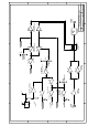
B. PA501 Factory Alignment and Test (Rev 30/9137)
B.1 Equipment Required
• Spectrum Analyser and tracking generator (eg Tektronix 492 with TR503)
• 150W, 50Ω Attenuator/load, 40dB attenuation
• Calibrated test Load with 5db return loss
• Calibrated test Load with 8dB return loss
• 13.8 Volt, 30A power supply
• Rhode & Schwarz SMG 1GHz GPIB-programmable RF generator
• 15W 450-520MHz driving amplifier (minimum 13W at 515MHz)
• Directional Power meter
• HP437B GPIB-programmable Power Meter
• PC with PwrView test Software, GPIB cables, etc.
• Spectrol long insulated alignment tool
• Various 50Ω connection cables, adapters, etc.
B.2 Procedure
1. Adjust the DC power supply to 14 Volts (no load). Adjust the SMG generator for
output off (Level OFF), centre frequency to 500MHz (RF 500 MHz), address 28
(IEC-addr, 2, 8, Enter). Connect the generator output to sweep amplifier input.
Connect DC supply to sweep amplifier and the device under test (DUT). Connect
the Sweep Amplifier to the Directional Power Meter, and the Directional Power
Meter to the DUT input. Connect the 40dB attenuating load to the output. Set up
and zero the HP437B power meter. The meter should be set for an operating
frequency of 0.5GHz and a cal factor as indicated on the sensor head, typically
98.5%. Fix it to range 5, offset 40dB (1kW range). connect the Power meter to
the load.
Set the RFO pot for maximum output (RV2 to CW), REVPWR to Max (RV1
fully CW), and C12 and C35 to middle position, C43 and C44 to about 1/4 of
range, and C11 near to the max (down) position.