Eclipse Series RF Technology rfinfo@rftechnology.com.
CONTENTS CONTENTS Contents 1 Operating Instructions 1.1 Installation 1.1.1 Sub-rack Wiring Guidelines 1.2 Front Panel Indicators 1.3 Internal Adjustments 1.4 Amplifier I/O Connections 1.4.1 RF Input 1.4.2 RF Output 1.4.3 25 Pin Connector 4 4 4 5 5 6 6 6 6 2 Circuit Description 2.1 Block Overview 2.2 RF Amplifiers 2.3 Directional Coupler 2.4 Low Pass Filter 2.5 Power Control Circuits 2.6 RF Output Indicator 2.7 Over Temperature Protection 6 6 7 7 7 8 8 8 3 Field Alignment Procedures 3.
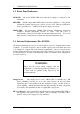
CONTENTS CONTENTS A Engineering Diagrams A.1 Block Diagram A.2 Circuit Diagrams A.3 Component Overlay Diagrams 14 14 14 14 B PA501 Factory Alignment and Test B.1 Equipment Required B.2 Procedure B.3 Checking Mismatched Loads 18 C Parts List C.1 PA501 Parts List for PCB-30/9137/xxxx C.
1 OPERATING INSTRUCTIONS WARNING Changes or modifications not expressly approved by RF Technology could void your authority to operate this equipment. Specifications may vary from those given in this document in accordance with requirements of local authorities. RF Technology equipment is subject to continual improvement and RF Technology reserves the right to change performance and specification without further notice.
1 OPERATING INSTRUCTIONS 1.2 Front Panel Indictaors 1.2 Front Panel Indicators PWR LED The power (PWR) LED shows that the dc supply is connected to the transmitter. RFO LED The RF output (RFO) LED indicates that the amplifier is being driven and that the forward output power is above a preset level. This preset indication level is generally set 1 - 3 dB below the preset output power level.
2 CIRCUIT DESCRIPTION 1.4 Amplifier I/O Connections The PA501 has three connectors on the rear panel. 1.4.1 RF Input The RF drive is delivered via a BNC connector. The absolute maximum power that should be applied to this connector is 17 Watts. 1.4.2 RF Output The RF output signal is available from an N-type connector.
2 CIRCUIT DESCRIPTION 2.2 Power Splitter / Combiners amplifier stage, and is followed by a lumped/distributed network that performs both impedance matching and power combining ahead of the output filter. The PA501 design is very broad band and will not usually require adjustment once it has left the factory unless components are changed or the equipment is required to move frequency from one extreme end of the band to the other.
2.5 Power Control Circuits (Rev 05/9151) The forward and reverse voltages from the directional coupler are amplified and inverted by Q103 and Q101. The amplified voltages are compared to preset reference levels and the comparison signals are combined in a logical fashion by Q109 and Q108 and used to produce the ALC signal. VR137 sets the maximum permitted reverse power level.
3 3 Field Alignment Procedures 3.1 Output Power Level Field Alignment Procedures (Rev 05/9151) Section 3.1 below describes how to adjust the PA501 amplifier for a particular output power level. Section 3.2 broadly describes how to align the PA501 matching circuits. This second procedure should not be necessary except after repair of a damaged unit, and requires specialised equipment. It should not be undertaken without appropriate tools and equipment. 3.1 Output Power Level 1.
4 SPECIFICATIONS 4.1 Description 1. Set the unit up on a bench with the test equipment as given in table 3 2. Disable the ALC loop 3. Connect the output of the 15 Watt source directly to the annenuator, bypassing the PA501 amplifier. 4. If you are using a network analyser, carry out calibration according to the instruments instructions so as to obtain a 0 dB display from about 425MHz to 525MHz. Set the sweep time to no less than 0.2s, and the stimulus power to +42 dBm (15W).
4 SPECIFICATIONS 4.5 Antenna Impedance The regulated power level can be preset over a wide guaranteed range from 25 to 120 Watts or more, depending on the available driver power. Sensing circuits are provided to protect the output transistors from excessive temperature. If the heat sink temperature rises to 90C, the input drive will be reduced to prevent damage. 4.2 Physical Configuration The power amplifier is designed to fit in an RF Technology sub-rack within a 19" rack frame.
4.4.2 Frequency Range 4.4.2 Model PA501A PA501B 4 SPECIFICATIONS Frequency Range Frequency Range 400-450MHz 450-512MHz 4.5 Antenna Impedance Nominal load impedance is 50Ω SWR 1.5:1 or better. The PA501 will operate with a VSWR of 2:1 at all phase angles. The forward power will reduce as reverse power rises above acceptable limits, typically at an SWR of about 2.5:1. 4.6 Output Power Nominally 100 Watts, preset adjustable from 25 to 120, typically 125 Watts maximum. Gain is >8.5dB. 4.6.
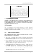
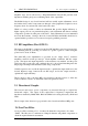
4 SPECIFICATIONS 4.10 Connectors 4.10.1 RF Input The RF drive is delivered via a BNC connector. The maximum power that should be applied to this connector is 17 Watts. 4.10.2 RF Output The RF output signal is available from an N-type connector. 4.10.3 25-Pin Connector A 25-pin, “D” connector provides connection to ground and dc power, and from the automatic level control (ALC) circuit. The pin connections are given in table 1.
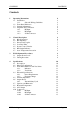
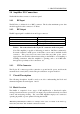
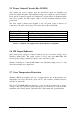
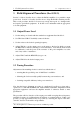
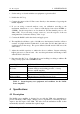
A ENGINEERING DIAGRAMS A Engineering Diagrams Where engineering diagrams are sufficiently complicated, large scale versions are included as inserts or fold-outs elsewhere in the manual for reading convenience. If inserts are missing or damaged, the information is identical to that presented in figures embedded in the text. A.1 Block Diagram Figure 1 shows the block signal flow diagram of the PA501 amplifier. A.
A B C D 1 1 5-15W INPUT J2 BNC R.F.DET. FWD.PWR. FAN OVER TEMP. RT1 90 DEG.C. REF. REG. U5 +13.8 Vdc Q7 FAN CONTROL 2 DRIVER AMPLIFIER Q3 U3D,Q5 RF OUTPUT INDICATOR U3C,Q6,Q8 t U3B SET RFO THRESHOLD +8.0 V.REF. Q9 OVER TEMP. DETECTOR +8.0 V.REF. 2 3 Q1 Q2 RV2 +8.0 V.REF. 4 4 REV.PWR. U2D DIRECTIONAL COUPLER D1-D3 FWD.& REV. POWER CONTROL U2A RV1 +8.0 V.REF. SET MAX REVERSE POWER ALC AMP U3A SET FORWARD POWER OUTPUT AMPLIFIER Q4 OVER TEMP.
A B C D 1 1 1 6 2 7 3 8 4 9 5 +13.8 1 14 2 15 3 16 4 17 5 18 6 19 7 20 8 21 9 22 10 23 11 24 12 25 13 0V A.L .C. +13.8 CONNE CT OR DB 25 P5 - 0V I cA I cB RF.DE T . OV E R T E MP. FWD.PWR. RE V .PWR.
B.1 Equipment Required B PA501 FACTORY ALIGNMENT AND TEST B. PA501 Factory Alignment and Test (Rev 30/9137) B.1 Equipment Required • Spectrum Analyser and tracking generator (eg Tektronix 492 with TR503) • 150W, 50Ω Attenuator/load, 40dB attenuation • Calibrated test Load with 5db return loss • Calibrated test Load with 8dB return loss • 13.
A ENGINEERING DIAGRAMS 2. Record serial number, etc., on the rest report sheet. 3. Inspect the module. Check the disposition of flying cables (clear of RF power compone nts). 4. Switch the Generator output level to 3dBm (LEVEL 3 dBm/enter). Adjust C43, 44, 11, 12, 35 for output power of at least 100W on the power meter. Switch off the generator (LEVEL OFF). The purpose of this step is simply to get the adjustments approximately correct before moving to the swept alignment stage. 5.
A ENGINEERING DIAGRAMS point). Measure and record the supply current, which should be below 25A (typically 21A). Measure and record the voltage drop across the collector current sense resistors (R21, R52, R53). The calculated supply current to Q2 and Q3 should be within 1A of each other. 10. Measure the input RF (driving) power level. the forward power level should be less than 14W. The reflected power level should be less than 1/5 of the forward power.
B PA501 FACTORY ALIGNMENT AND TEST B3 Checking Mismatched Loads B3 Checking Mismatched Loads The correct operation of the calibrated mismatch loads may be checked using the equipment available for other tests. Place the Directional Power Meter between the driving amplifier and the load to be tested. Adjust the generator to 500MHz, output on. Measure the forward and reverse powers. The return loss is calculated at RL = 10 log (PR/PF).
C PA501 PARTS LIST C - PA501 Parts List for PCB - 30/9137/xxxx Main PCB Assembly Parts, (common to all variants) Ref.
C PA501 PARTS LIST Ref. Description Part Number C61 C62 C63 C64 C65 C201 D1 D2 D3 D4 D5 J3 J4 JP1 L1 L2 L3 L4 L5 L6 L7 L8 L9 L10 L11 L12 L13 L14 L15 P1 P2 Q1 Q2 Q3 Q4 Q5 Q6 Q7 Q8 Q9 R9 R10 R11 R21 R26 R27 R28 R29 R30 R31 R32 R33 R34 R35 R36 R37 R38 R39 Capacitor 100P 5% 63V NPO 1206 Capacitor 100P 5% 63V NPO 1206 Capacitor 10U 35V RAD Electro Capacitor 100N 10% 63V X7R 1206 Capacitor 10N 10% 63V X7R 1206 Capacitor 100N 10% 50V X7R RD.
C PA501 PARTS LIST Ref. R36 R37 R38 R39 R40 R41 R42 R43 R44 R45 R46 R47 R48 R49 R50 R51 R52 R53 R54 R55 R56 R57 R58 R59 R60 R61 R62 R63 R64 R65 R66 R67 R68 R69 R70 R71 R72 R73 R74 R75 R76 R77 R78 R79 R80 R81 R82 R83 R84 R85 RT1 RV1 RV2 RV3 U2 U3 U5 L201 R201 Description Resistor 22K 5% 0.25W SM1206 Resistor 10K 5% 0.25W SM1206 Resistor 330K 5% 0.25W SM1206 Resistor 10K 5% 0.25W SM1206 Resistor 22K 5% 0.25W SM1206 Resistor 10K 5% 0.25W SM1206 Resistor 470K 5% 0.25W SM1206 Resistor 470K 5% 0.
C PA501 PARTS LIST PA501 Parts List for PCB – 30/9151/xxxx Main PCB Assembly Parts, (common to all variants) Ref.
C PA501 (PCB 30/9151/xxxx) PARTS LIST Ref. Description C115 D100 D101 D102 D103 J3 J4 JP1 L1 L2 L3 L4 L6 L7 L8 L9 L10 L11 L12 L13 L14 L15 L100 P1 P2 Q1 Q2 Q3 Q6 Q100 Q101 Q102 Q103 Q104 Q105 Q106 Q107 Q108 Q109 Q111 Q112 Q113 Q114 Q115 Q116 Q117 R21 R26 R29 R30 R31 R32 R33 R34 R43 R52 R53 R54 R55 R56 R57 Capacitor 1N0 5% 63V NPO SM1206 Diode Shottkey BAT17 SOT23 Diode Shottkey BAT17 SOT23 Diode Dual GP BAV99 SOT23 Diode Dual GP BAV99 SOT23 2.8mm QC TAB Vertical PCB Mount 2.
C PA501(PCB 30/9151/xxxx) PARTS LIST Ref. R66 R73 R76 R80 R81 R85 R100 R101 R102 R103 R104 R105 R107 R108 R109 R110 R111 R112 R113 R114 R115 R116 R117 R118 R120 R121 R122 R123 R124 R125 R126 R127 R128 R129 R130 R131 R132 R133 R134 R136 R137 R138 R139 R141 R142 R145 R146 R147 R148 R150 R151 R152 R153 R154 R156 R157 R158 R159 RT1 Description Resistor 470R 5% 0.25W SM1206 Resistor 10R 5% 0.25W SM1206 Resistor 270 5% 0.25W SM1206 Resistor 1K0 5% 0.25W SM1206 Resistor 270 5% 2W Axial Resistor 1R0 5% 0.
C PA501 (PCB 30/9151/xxxx)PARTS LIST Ref.
1 2 3 4 5 6 +8.0 +13.6B R56 IC B R53 0R022 C56 10N +13.6C R49 100K OVER TEMP. R51 + 100 C57 100P U3A TLC274 +13.8 - 3 R11 2 100 TLC274 U2A 11 P2 +8.0 4 J3 1 R50 47K R68 100K C54 D5 BAV99 0 4K7 10 0 +13.8 R54 +13.6C #L201 L11 C31 1N0 + C30 220P + 33K R84 1K R39 9 10 C50 100P R40 22K C51 100P R41 10K C41 * C35 14P C29 * +13.6B D1 BAT17 C38 C23 C92 C93 * * * * C13 220P C22 6U8 C18 220P L7 * C101 C20 1N0 + C21 100N R34 4.
1 2 TP4 +13.8 TP1 R52 0R022 P1 3 4 5 6 8 7 +13.6A R55 IC A C58 1N0 +13.8 100 TP2 R21 0R022 +8V R85 1R0 R56 IC B D R80 1K0 100 TP3 C100 10N IC C J4 100 270 R81 270 1W R150 10k R146 10k R66 C112 470 27p R158 10 RT144 B59901/D90 OVERTEMP FAN Q115 MMBT3904 Q116 MMBT3904 P2 R151 22k Q114 MMBT3906 VR143 10k R145 10k TEMP.LED R57 13.8 R138 560 R141 10k MMBT3904 Q117 R76 +13.6C R156 10k MMBT3906 Q113 Q112 MMBT3906 Q6 TIP32 R53 0R022 R157 10k R147 10 +13.