
Operating instructions


Page 8 RF Technology R350/R500
4 FREQUENCY PROGRAMMING
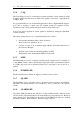
2.8 JP11: EPROM Type
Condition Position
27C256 2-3 *
27C64 1-2
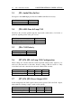
2.9 JP13: Squelch Defeat (pcb 30/9131/0004 or later)
Normal squelch can be defeated with an active low signal at DB-25 pin 19.
Condition Position
Squelch operation normal 1-2 *
Squelch Defeat 2-3
2.10 JP19: LED Alarm o/p (pcb 30/9131/0004 or later)
The LED alarm can be brought out to DB-25 pin 7 for ATI
Condition Position
No Alarm Output 1-2 *
Alarm LED connect to DB-25 pin 7 2-3
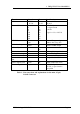
3 Receiver I/O Connections
3.1 25 Pin Connector
The D-shell 25 pin connector is the main interface to the receiver. The pin connections
are described in table 3.
4 Frequency Programming
Channel frequency and subtone frequency settings are maintained in non-volatile
memory for each of the 100 channels. Channel frequency and subtone frequency
programming is most easily accomplished with RF Technology TecHelp/ Service
Monitor software. This software can be run on an IBM compatible PC and provides a
number of additional useful facilities. DOS and MS Windows versions are available.
TecHelp/ Service Monitor allows setting of the adaptive noise squelch threshold,
provides a simple means of calibrating the signal strength output and minimum signal
alarm.
TecHelp/ Service Monitor can be supplied by your dealer, distributor or by contacting
RF Technology direct.