
Operating instructions


Page 6 RF Technology R350/R500
2 RECEIVER INTERNAL JUMPER OPTIONS
issue 4 and lower use the LED flash rate to indicate the alarm condition. Refer to table
2.
LED Flash Cadence Fault Condition
5 flashes, pause Synthesizer unlocked
4 flashes, pause Tuning voltage outside limits
3 flashes, pause Signal level below preset threshold (fixed link)
1 flash, pause dc supply voltage low or high
LED ON continuously External squelch is active
Table 1: Interpretations of LED flash cadence
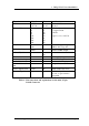
Indication Fault condition
Flashing, 8 per second Synthesizer unlocked
Flashing, 4 per second Tuning voltage outside 2-7 Vdc
Flashing, 2 per second Signal level below preset threshold (fixed links)
Continuous dc supply voltage low or high
Table 2: Interpretations of LED flash speed, for early models.
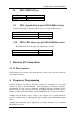
2 Receiver Internal Jumper Options
In the following subsections an asterisk (*) signifies the standard (Ex-Factory)
configuration of a jumper.
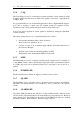
2.1 JP1: 240 Hz Notch Filter
JP1 allows the 240Hz notch filter in the normal audio path to be bypassed.
Condition Position
Notch Filter In 1-2 *
Notch Filter Out 2-3
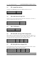
2.2 JP2: Audio Response
Condition Position
750 uSec. de-emphasis 1-2 *
Flat response 2-3