
Operating instructions


RF Technology R350/R500 Page 5
1.1 Front Panel Controls and Indicators 1 OPERATING INSTRUCTIONS
1.1.4 C.SQ
The C.SQ trimpot is used to set the carrier squelch sensitivity. Carrier squelch is useful
at higher signal levels than those at which noise squelch can be used – typically from
1-200µ V input.
It is provided mainly for use in fixed link applications where a high minimum signal to
noise ratio is required or where very fast squelch operation is required for data
transmission. The carrier squelch will open and close in less than 2~ms.
In most base station applications carrier squelch is disabled by turning the adjustment
counter clockwise.
The carrier squelch may be set to a predetermined level as follows:
1. First turn the adjustment fully counter-clockwise.
Then set the noise squelch as above.
2. Connect a source of an on channel signal with the desired threshold level to
the receiver's RF input.
2. Turn the screw clockwise until the SQ LED goes OFF.
Then turn the screw back until the LED just comes ON.
1.1.5 LINE
The LINE trimpot is used to set the line and direct audio output level. It is normally set
so that 0dBm (775mV) with a standard input signal gives 60% of maximum deviation
at 1 KHz. The level can be measured between test socket pins 6 and 1 and set as
desired.
1.1.6 POWER LED
The Power LED shows that the dc supply is connected to the receiver.
1.1.7 SQ LED
The SQ LED comes on when the audio to the line and direct outputs is unsquelched.
The LED and squelch function are controlled by noise, carrier and tone squelch
circuits.
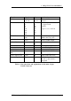
1.1.8 ALARM LED
The Alarm LED can indicate the detection of several different fault conditions by the
self test circuits. The alarm indicator shows the highest priority fault present. Receivers
using software issue 5 and higher use the cadence of the LED flash sequence to indicate
the alarm condition. Refer to table 1. Receivers using software