
Operating instructions


Page 22 RF Technology R350/R500
A ENGINEERING DIAGRAMS 7.5 Connectors
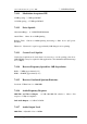
7.4.22 External Squelch Input
An external input is provided to squelch or mute the receiver audio output. This may
be used in conjunction with an external decoder or to mute the receiver during
transmissions.
External Squelch Input can be connected to the T/R Relay pin on Eclipse transmitters
to mute the receiver during transmission.
7.5 Connectors
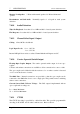
7.5.1 Antenna Connector
Type N Female Mounted on the module rear panel
7.5.2 Power & I/O Connector
25-pin “D” Male Mounted on the rear panel
7.5.3 Test Connector
9-pin “D” Female mounted on the front panel
A Engineering Diagrams
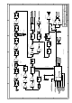
A.1 Block Diagram
Figure 1 shows the block signal flow diagram.
A.2 Circuit Diagram
Figure 2 shows the detailed circuit diagram with component numbers and values.
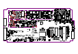
A.3 Component Overlay Diagram
Figure 3 shows the PCB overlay guide with component positions.