
Operating instructions

RF Technology T350/T500 Page 9
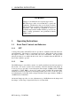
2 TRANSMITTER INTERNAL JUMPER OPTIONS 2.10 JP17: Bypass Low Pass Filter
Condition Position
Normal Tone Input 1-2*
Direct Tone Input 2-3
2.10 JP17: Bypass Low Pass Filter
(pcb 30/9103/0009 or later)
Some trunking controllers have digital encoding schemes that require the low pass filter
in the tone input section to be bypassed. JP17 allows this. Normally JP17 is open
circuit. Placing a link across it will bypass the low pass filter.
In conjunction with this change, it sometimes may be necessary, depending upon the
type of trunking controller used, to add a 100K resistor in the place reserved for R157.
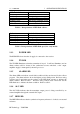
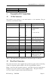
2.11 JP19: Alarm Output (pcb 30/9103/0009 or later)
The main audio transformer (T1), is connected to the Line IPI and Line IP4 pins on P3.
These two pins constitute the main audio input for the exciter. The centre taps of the
audio transformer, though, are brought out on Line IP2 and Line IP3. These can be
used as alternate audio inputs for larger signals, or to directly access the dc loop sense
circuitry. JP19 allows an alternate use for Line IP2 (pin 7 of P3). In the alternate
position for JP19, the ALARM signal (the signal that drives the ALARM LED itself) is
connected to pin 7 of P3. The ALARM signal when asserted is low active; when
unasserted it pulls high to +9.4V through an LED and a 680 ohm resistor.
Condition Position
P3, pin 7 connects to centre tap of transformer T1 1-2*
P3, pin 7 connects to ALARM signal 2-3
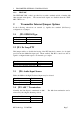
2.12 JP22: Use Tone- as a Direct Digital Input
(pcb 30/9103/0009 or later)
JP22 is normally shunted with a jumper, which connects Tone- on P3 (pin 18), as the
negative leg of the Toner input pair. Removing this jumper disconnects Tone- from
this path and allows the use of the Tone- pin to be used as s direct digital input. See
also 2.9 - JP16: If the jumper is removed, then JP16 should be in the alternative position
(Direct Tone Input).
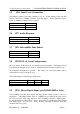
2.13 JP23: Connection of DMTX Board
(pcb 30/9103/0009 or later)
When the DMTX board is connected to an exciter, there is provision for digital or audio
modulation of the reference oscillator and VCO. The digital signal is input via the DB9
rear connector and the audio input signal is via the Line inputs on the standard DB25
rear panel connector.