
Operating instructions

RF Technology T350/T500 Page 8
2.5 JP6: Input Level Attenuation 2 TRANSMITTER INTERNAL JUMPER OPTIONS
2.5 JP6: Input Level Attenuation
This jumper permits coarse input sensitivity to be set. In the default position, the unit
expects a line level of 0dBm (nominal) at its Line Input. In the alternate position,
levels of +20dBm (nominal) can be accepted.
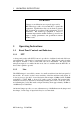
Condition Position
0dB attenuation 1-2 *
20dB attenuation 2-3
2.6 JP7: Audio Response
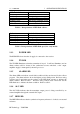
Condition Position
750 uSec. pre-emphasis 1-2 *
Flat response 2-3
2.7 JP8: Sub-audible Tone Source
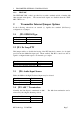
Condition Position
Internal CTCSS 1-2, 4-5 *
External input 2-3, 5-6
2.8 JP9/10/11: dc Loop Configuration
DC loop current on the audio pair, is normally sourced externally. The Eclipse exciters
loop the current through an opto-isolator. when the current flows the exciter keys up.
An alternative arrangement is possible. The exciter can source the current and an
external device can provide the dc loop.
These three jumpers select the appropriate mode.
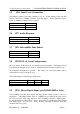
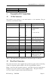
Condition JP9 JP10 JP11
Current Loop Input ON OFF OFF *
12Vdc Loop source OFF ON ON
2.9 JP16: Direct Digital Input (pcb 30/9103/0009 or later)
Some trunking controllers have digital encoding schemes which operate to very low
frequencies. The elliptical filter, used as a 250Hz low pass filter in the tone section,
can cause excessive pulse edge distortion of the truinking controller’s digital signals.
In such circumstances, JP16 allows a user to bypass the low and high pass filters in the
tone input section. See also 2.12 - JP22: If direct tone input is selected, then JP22
should be removed (open).