
Operating instructions

RF Technology T350/T500 Page 2
CONTENTS CONTENT
Contents
1 Operating Instructions 5
1.1 Front Panel Controls and Indicators 5
1.1.1 PTT 5
1.1.2 Line 5
1.1.3 PWR LED 6
1.1.4 TX LED 6
1.1.5 ALARM LED 6
1.1.6 ALC LED 6
1.1.7 REF LED 6
1.1.8 TEST MIC 7
2 Transmitter Internal Jumper Options 7
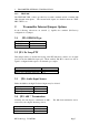
2.1 JP2: EPROM type 7
2.2 JP3: Dc Loop PTT 7
2.3 JP4: Audio Input Source 7
2.4 JP5: 600? Termination 7
2.5 JP6: Input Level Attenuation 8
2.6 JP7: Audio Response 8
2.7 JP8: Sub-audible Tone source 8
2.8 JP9/10/11: dc Loop Configuration 8
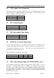
2.9 JP16: Direct Digital Input (Rev 4 or Higher) 8
2.10 JP17: Bypass Low Pass Filter (Rev 4 or Higher) 9
2.11 JP19: Alarm Output (Rev 4 or Higher) 9
2.12 JP22: Use Tone- as a Direct Digital Input (Rev 4 or Higher) 9
2.13 JP23: Connection of DMTX Board (Rev 4 or Higher) 9
3 Transmitter I/O Connections 10
3.1 25 Pin Connector 10
3.2 Rear Panel Connectors 10
4 Channel and Tone Frequency Programming 12
5 Circuit Description 12
5.1 VCO Section 12
5.2 PLL Section 12
5.3 Power Amplifier 13
5.4 Temperature Protection 13
5.5 600Ω line Input 13
5.6 Direct Coupled Audio Input 13
5.7 Local Microphone Input 14
5.8 CTCSS and Tone Filter 14
5.9 Audio Signal Processing 14
5.10 PTT and DC Remote Control 15
5.11 Micro-processor Controller 15
5.12 Voltage Regulator 16
6 Field Alignment Procedure
6.1 Standard Test Conditions 16
6.2 VCO Alignment 17