
Operating instructions

RF Technology T350/T500 Page 10
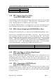
3 TRANSMITTER I/O CONNECTIONS
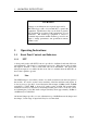
Condition Position
N DMTX board 1-2, 5-6*
DMTX board connected 2-3, 4-5
3 Transmitter I/O Connections
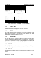
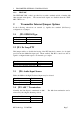
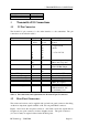
3.1 25 Pin Connector
The D-shell 25 pin connector is the main interface to the transmitter. The pin
connections are described in table 3.
Function Signal Pins Specification
DC power +12 Vdc
0 Vdc
1, 14
13, 25
+11.4 to 16 Vdc
Ground
Channel Select 1
2
4
8
10
20
40
80
21
9
22
10
23
11
24
12
BCD Coded
0 = Open Circuit
or 0 Vdc
1 = +5 to +16 Vdc
RS232 Data In
Out
15
2
Test and Programming use
9600, 8 data 2 stop bits
600Ω Line
High
Low
20
6
Transformer Isolated
Balanced 0dBm Output
150Ω / Hybrid
7
19
Direct PTT input 3 Ground to key PTT
T/R Relay driver output 16 Open collector,250mA/30V
Sub-Audible Tone Input [+] 5
>10kΩ, AC coupled
[-] 18 (1-250Hz)
High-Z Audio Input [+] 4
>10kΩ, AC coupled
[-] 17 (10Hz-3kHz)
External ALC input 8 <0.5V/1mA to obtain
>30dB attenuation, O/C
for maximum power
Table 3: Pin connections and explanations for the main 25-pin, D connector.
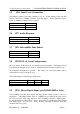
3.2 Rear Panel Connectors
The exciter and receiver can be supplied with optional rear panel connectors that bring
out the more important signals available on P1, the rear panel DB25 connector.
Figures 1 and 2 show the rear panel connectors, and Table 4 shows the signals that are
brought out onto spade connectors for these daughter boards. The spade connectors
(2.1 x 0.6 x 7mm) are captive/soldered at the labelled points.