
Operating instructions


Page 10 RF Technology R350/R500
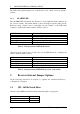
3 RECEIVER I/O CONNECTIONS 3.1 25 Pin Connector
3 Receiver I/O Connections
3.1 25 Pin Connector
The D-shell 25 pin connector is the main interface to the receiver. The pin
connections are described in table 3.
Function Signal Pins Specification
DC Power +12 Vdc
0 Vdc
1, 14
13, 25
+11.4 to 16 Vdc
Ground
Channel Select 1
2
4
8
10
20
40
80
21
9
22
10
23
11
24
12
BCD Coded
0 = Open Circuit
or 0 Vdc
1 = +5 to +16 Vdc
RS232 Data In
Out
15
2
Test and Programming use 9600,
8 data 2 stop bits
600Ω Line
In
Out
20
6
Transformer Isolated Balanced
0dBm Output
150Ω / Hybrid
7
19
Discriminator 18 AC coupled, unsquelched
Direct Audio Output 17 Direct AC Coupled Audio
Audio Ground 5 Direct Audio Ground
Sub-Audible Audio
Out
4 Unsquelched, 1-250 Hz
Carrier Operated Sw
Carrier Operated Sw
COS [+]
COS [-]
3
16
Opto-coupled Transistor Switch
(10mA 30V max)
External Squelch Input 8 <1 Vdc to Squelch
>2 Vdc or open ckt to
unsquelch
Table 3: Pin connections and explanations for the main, 25-pin,
D-shell Connector