
User's Manual


Eclipse2 Technical Manual, 3-Aug-12 Page 8 of 17
Operation
The Reciter will need approximately 30 seconds to boot up after power up. When the transceiver is
re
ad
y
to operate, a voice report (if enabled) can be heard from the front panel speaker, and the
Digital/Analog LED will indicate the current operational mode.
Front Panel Controls and Indicators
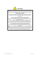
The front-panel includes LED indicators, tactile switch buttons, a microphone connector and an USB
(type A) connector, refer figure.1 for details
Figure1: Eclipse2 Transceiver Front panel
Buttons:
Status – Press this button to listen to the voice report
Tes
t – Press this button to key up the exciter (if front panel test key enabled)
Up – Press this button to increase the speaker volume
Down – Press this button to decrease the speaker volume
Left – Press this button to channel change down
Right – Press this button to channel change up
Reset – The reset switch mounted inside base station, used for reset the Reciter without
power cycle, use a small pin (e.g. paper clipper) to access this switch
Indicators:
Power – This LED (on) indicates that DC power supply is applied to the Reciter
Eth
ernet – This LED (on) indicates that the transceiver is operating in Digital mode
Analog – This LED (on) indicates that the transceiver is operating in Analog mode, - if the
transceiver is operating in dual mode, both Digital and Analog LED will be on
Tx – This LED (on) indicates the transceiver’s transmitting path is active
Rx – This LED (on) indicates the transceiver’s receiving path is active
Alarm – This LED (flash) indicates the transceiver is in alarm state, press the status button
to listen the alarm information
Connectors:
Microphone – RJ45 connector for front-panel microphone input
USB – USB (type A) connector for connecting a PC via a standard USB cable to monitor or
program the Reciter.
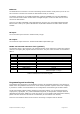
Rear Panel Connectors
System I/O:
The male D shell, 25-pin connector is the main interface to the Reciter Module. The pins of the
con
nection are described in table 1.