
User's Manual

ECLIPSE2 IPCommander User Manual
19
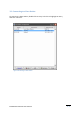
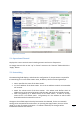
When receiving a valid analog signal the RX path will be highlighted in green. Blue
highlighting indicates a valid P25 signal.
5.8. RSSI
Displays the Received Signal Strength in dBm.
5.9. C/N
Displays the current RF Carrier to Noise Ratio in dB.
5.10. Channel Bandwidth
Displays the current channel bandwidth. 12.5KHz or 25KHz.
5.11. RX P25 NAC
Displays the current decoded RX NAC.
Only displayed when the C4FM demodulator is present on the signal map.
5.12. RX P25 BER
Displays the Bit Error Rate of the P25 Demodulator.
Only displayed when the P25 demodulator is present on the signal map.
5.12.1. RX VCO
Shows current RX VCO tuning voltage and PLL frequency.
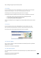
5.13. TX Path
When transmitting an analog signal, the TX path will be highlighted in orange. Pink
highlighting means a P25 signal is being transmitted.
5.14. Forward Power
Displays the forward power at the Exciter output.
5.15. Reverse Power
Displays the reverse power at the Exciter output.