
User's Manual


Eclipse2 Technical Manual V1.5 Page 9 of 16
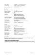
21 Monitor speaker output Output: unbalanced 8 ohm
300 to 3000Hz, 3 Watt maximum
9 System serial bus, Data in Input: +3.3V TTL logic
22 System serial bus, CS0 Output: +3.3V TTL logic
10 System serial bus, CS1 Output: +3.3V TTL logic
23 T/R relay output Output: open collector, Imax = 100mA
11 External squelch input
Input: Low active (Vin
≤
+2.5V)
24 Spare GPIO input
Input: Low active level
≤
+2.5V)
12 Spare GPIO output Output: open collector, Imax = 100mA
Table1: 25 Pin System I/O Connector signals
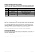
4 Wire E&M Port
This RJ45 connector provides easy connection to the equipment such as microwave links, the signal
of the E/M line connector described in table2.
Pin No. Description Specification
1 E+ Input: 10V to 48V
2 E- Input: 10V to 48V
3 Line out + Output: balanced 600ohm,
300 to 3000Hz, -20dbm to +10dbm
4 Line out - Output: balanced 600ohm,
300 to 3000Hz, -20dbm to +10dbm
5 Line in + Input: balanced 600ohm,
300 to 3000Hz, -20dbm to +10dbm
6 Line in - Input: balanced 600ohm,
300 to 3000Hz, -20dbm to +10dbm
7 M+ Output: sink current 150mA
8 M- Output: sink current 150mA
Table2: RJ45 E/M Line Connector signals
Ethernet:
The RJ45 Ethernet connector is used for networking the base station via IP protocol, a PC can use
this connector to monitor and control the base station locally or remotely.
The Reciter supports the 10/100Mbs specification (defined by IEEE802.3u) and the MDI/MDI-X
auto crossover function which means either a straight though or crossover cable can be used to
connect the base station.
There are two LEDs embedded in the RJ45 Ethernet connector, the green LED indicates that the
Ethernet link is active; the yellow LED indicates TX/RX status between the base station and the
network.
RF input:
The receiver RF input connector: 50ohm female, N type.
RF output:
The exciter RF output connector: 50ohm female SMA or Optional N type.