
User's Manual


Eclipse2 Technical Manual V1.5 Page 8 of 16
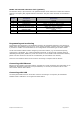
Figure1: Eclipse2 Transceiver Front panel
Buttons:
Status – Press this button to listen to the voice report
Test – Press this button to key up the exciter (if front panel test key enabled)
Up – Press this button to increase the speaker volume
Down – Press this button to decrease the speaker volume
Left – Press this button to channel change down
Right – Press this button to channel change up
Reset – The reset switch mounted inside base station, used for reset the Reciter without
power cycle, use a small pin (e.g. paper clipper) to access this switch
Indicators:
Power – This LED (on) indicates that DC power supply is applied to the Reciter
Ethernet – This LED (on) indicates that the transceiver is operating in Digital mode
Analog – This LED (on) indicates that the transceiver is operating in Analog mode, - if the
transceiver is operating in dual mode, both Digital and Analog LED will be on
Tx – This LED (on) indicates the transceiver’s transmitting path is active
Rx – This LED (on) indicates the transceiver’s receiving path is active
Alarm – This LED (flash) indicates the transceiver is in alarm state, press the status button
to listen the alarm information
Connectors:
Microphone – RJ45 connector for front-panel microphone input
USB – USB (type A) connector for connecting a PC via a standard USB cable to monitor or
program the Reciter.
Rear Panel Connectors
System I/O:
The male D shell, 25-pin connector is the main interface to the Reciter Module. The pins of the
connection are described in table 1.
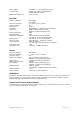
Pin No. Description Specification
1, 4 Power supply, positive Input: +13.8VDC
(minimum 10.8V, maximum 16V)
13,25 Power supply, negative Input: Ground
2 System serial bus, Data out Output: +3.3V TTL logic
15 System serial bus, Clock Output: +3.3V TTL logic
3 Exciter PTT input
Input: Low active level
≤
+2.5V)
16 Receiver COS output Output: open collector, Imax = 100mA
4 AUX audio input Input: unbalanced 4.7kohm, DC to 3000Hz
5 AUX audio output Output: unbalanced 4.7kohm, DC to 3000Hz
8, 17 Audio signal ground Input: ground
6 Line input + Input: balanced 600ohm,
300 to 3000Hz, -20dbm to +10dbm
19 Line input - Input: balanced 600ohm,
300 to 3000Hz, -20dbm to +10dbm
7 Line output + Output: balanced 600ohm,
300 to 3000Hz, -20dbm to +10dbm
20 Line output - Output: balanced 600ohm,
300 to 3000Hz, -20dbm to +10dbm
8 GPS 1 pulse/sec input Input: +3.3V to +15V TTL logic