
User's Manual


Eclipse2 Technical Manual V1.5 Page 10 of 16
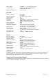
RS232 and external reference clock (optional)
The female D shell, 9-pin connector is an optional interface to the transceiver. RS232 and external
reference clock (EXT_REF) signals share this connector. The pins of the connector are described in
table 3.
Pin No. Description Specification
1 GND(RS232) Ground
2 TXD (RS232) Output: +/-5V to +/-15V TTL logic
3 RXD(RS232) Input: +/-5V to +/-15V TTL logic
5 GND(RS232) Ground
8 External reference clock Input, sine wave or TTL logic,
Minimum input: 0.5Vp-p
9 GND(EXT_REF) Ground
4, 6, 7 NC No connection on pin 4, 6, 7
Table2: RJ45 E/M Line Connector signals
Programming and monitoring
Programming and monitoring is accomplished using the IP Commander Software. This software is
based on the Java platform and can be run under various operation systems on the host computer,
it provides a number of useful facilities for the configuration and monitoring of the base station.
The IP Commander software allows configuring of the base station (e.g. the channel frequency,
output power, signal path, etc.) without hardware alignment, it also provides a simple means of
calibrating the RF power, RSSI level, audio line levels. For more details of IP Commander software,
please refer the document: RFT Doc No. 0305917801 (IP Commander User Manual).
There are two interfaces which can be used for connecting a computer and the Reciter:
Connecting with Ethernet
Ethernet is the interface of the base station, especially for remote monitoring and controlling via an
IP Network. Each base station has a unique IP address, to connect, the host PC must be in the
same subnet with the base station.
Connecting with USB
The front-panel USB connector can be also used for connecting to a computer, IP Commander
Software loads a USB driver to recognize the base station.