
User's Manual


Page 12 RF Technology
A ENGINEERING DIAGRAMS
4.10.2 RF
Output
The RF output signal is available from an N-type connector.
4.10.3 25-Pin
Connector
A 25-pin, D-shell (“D”') connector is mounted on the rear panel. It provides power
connections only. The pin connections are given in table 1.
4.10.4 USB
Connector
A front-panel, Universal Serial Bus connector (Type A) provides fast configuration and
firmware upgrades.
A Engineering Diagrams
A.1 Block Diagram
Attachment A.1 shows the signal flow diagram of the IP
•
PA500BH amplifier.
A.2 Circuit Diagrams
Attachment A.2 shows the chassis wiring diagram of the amplifier.
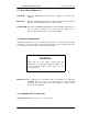
RF Exposure.
This amplifier constitutes part of a RF transmitting system that both the FCC and Industry Canada has
established RF exposure requirements for. In order to comply with the RF exposure requirements of both
countries the transmitting antenna must maintain a specific physical separation from all persons.
The antennas for this device usually are mounted on outdoor permanent structures and the installer must
see that the separation distance be maintained. The RF exposure report was written for one typical power
output and antenna gain. If your situation is different than the one described your minimum separation
distance will be different. RF exposure takes into account many different contributing factors some
of which are: power output, system losses, coax cable losses, and antenna gain.
For a typical installation of a 3 dBi antenna and 120 W UHF band (450-512 MHz) transmitter. Operated
in a radio system were the average ratio of transmit to receive time is near 100% transmitting the
separation distance would be 2.2 meters or approximately 7 feet. This separation distance also
does not take into account any other transmitters that might be considered co-located at the same site.
An RF exposure report was prepared for this amplifier and in it are the typical calculations on which the
above is based.
E2-IP-PA 500BH