
Operations Manual


RF Technology R50 Page 9
4 CHANNEL PROGRAMMING AND OPTIONS SELECTIONS
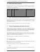
3.2 9 Pin Front Panel Connector
The female D-shell, 9 pin, front panel connector is an RS232 interface for serial
communications to a terminal, a terminal emulator, or to a computer. The pin
connections are described in table 4.
Function Pins Specification Pin name on IBM PC
TXD 2 Transmit Data (Output) RxD
RXD 3 Receive Data (Input) TxD
RTS 8 Request To Send (Output) CTS
CTS 7 Clear To Send (Input) RTS
DTR 6 Data Terminal Ready(Output) DSR
DSR 1 Data Set Ready (Input) DCD
GND 5 GND GND
Table 4: Pin connections for the front panel 9 pin D connector
The pinout for the connector has been chosen so that a straight-through BD9 male to
DB9 female cable can connect the transmitter to any male DB9 serial port on an IBM
PC compatible computer.
Note that for connection to a modem, a cross-over cable will be required.
4 Channel Programming and Option Selections
Channel and tone frequency programming is most easily accomplished with RF
Technology Eclipse50 software. This software can be run on an IBM compatible PC
and can be used to calibrate a T50, R50, and PA50 as well as program channel
information. See the Eclipse 50 users manual for further information.
But the R50 also has its own stand-alone high level interface, which can be accessed
from a VT100 compatible terminal, or terminal emulator (such as HyperTerm which is
available as a standard accessory with Windows).
The pertinent aspects of this High Level Interface are described below.
4.1 Setting Options
Note that any text in italics, represents data output by the R50 firmware, rather than
command line data sent to the R50 firmware.
The R50, after powering up, will issue a command prompt of the form:
R50>
Via a terminal, or a terminal emulator, a user can type various commands in. The basic
command to read parameters is: