
Operations Manual


Page 8 RF Technology R50
3.1 25 Pin Connector
3 RECEIVER I/O CONNECTIONS
maximum line deviation to use, what tone deviation to use, what transmit delay (a
delay applied from PTT-in or LOOP-in to transmission), what transmit tail (delay
from PTT-in, or LOOP-in, to transmission being stopped, and No-TONE period (a
period of extra transmission in which No Tone is applied after PTT-in or LOOP-in has
been released.
As well as these parameters, which Line (or Lines) can be selected, and whether the
Lines should have Flat frequency response or have Pre-emphasis applied. Also, it can
Enable or disable the extra 20dB gain pad.
Note that both Line1 and Line 2 can be selected (each with or without pre-emphasis),
and if so, then the two signals will be mixed, and the Line potentiometer will adjust
the level of them both.
3 Receiver I/O Connections
3.1 25 Pin Connector
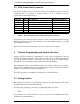
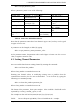
The female D-shell, 25 pin, connector is the main interface to the transmitter. The pin
connections are described in Table 3.
Function Signal Pins Specification
DC Power +28Vdc(in)
0 Vdc
+5Vdc(out)
+12Vdc(out)
13, 25
1, 14
17
15
+24 to 32 Vdc
Common Voltage
Output for external Logic(100mA)
Output for an external relay(120mA)
Serial
Communications
SCLK
MOSI
CH_EN
SPEARE_I/O1
SPARE_SEL
12
6
18
16
5
Serial Clock
Bi-directional Data Pin
Enables Channel Select Shift Register
Spare Input or Output (for future use)
Spare Select (for future use)
600Ω Line
Output
Line+
Line-
8
19
Transformer Isolated Balanced 600Ω
0dBm Output
Carrier Operated
Switch Output
COS+
COS-
10
22
Opto Coupled Transistor Switch
Output (10mA)
External Squelch
Input
EXT_SQ 11 <1 VDC to Squelch
>2 VDC or pen ckt to un-squelch
External Speaker
Output
EXT_SPK 24 AC Coupled External Speaker
Output, 5W @ 4Ω Load
Direct Audio
Output
DIR_AUD 21
>10kΩ, AC Coupled Audio Output
2Vp-p @ 3kHz System Deviation
Discriminator
Audio Output
DISC_AUD 20
>10kΩ, AC Coupled Un-Squelched
2Vp-p @ 3kHz System Deviation
Sub-Audible
Tone Output
SUBTONE
9
>10kΩ, AC Coupled Un-Squelched,
2Vp-p @ 3kHz System Deviation
Table 3: Pin connections and explanations for the main 25-pin, D connector