
Operations Manual


Page 6 RF Technology R50
1.2.2 SQ LED
2 RECEIVER OPTIONS
1.2.2.1
SQ LED
The SQ LED comes on when the audio to the line and direct outputs is un-squelched.
The LED and squelch function are controlled by noise, carrier and tone squelch
circuits.
1.2.3 ALARM LED
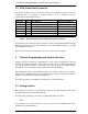
The ALARM LED can indicate several fault conditions if they are detected by the self
test program. The alarm indicator shows the highest priority fault present. See Table
1.
LED Flash Cadence Fault Condition
9 flashes, pause External PA failure
8 flashes, pause Low dc supply on External PA
7 flashes, pause External PA Over Current Condition
6 flashes, pause External PA Over Temperature
5 flashes, pause Synthesizer unlocked
3 flashes, pause Unable to communicate with External PA
2 flashes, pause The current channel is not programmed or the frequency
is out of range.
1 flash, pause Low dc supply voltage
LED ON continuously Transmitter timed out
Table 1: Interpretations of LED flash cadence
2 Receiver Options
There are many software selectable options. Some options are selected on a per
channel basis, and some are defined globally (i.e. the parameter is fixed irrespective of
which channel is selected). Below is a description of these global parameters
2.1 Serial I/O Parameters
There are two serial ports. There is the main serial port which is brought out to the
front panel connector. This is referred to as PORT0. There is another serial port
which is for factory use only. It is referred to as PORT1.
The baud rate, parity, and whether hardware flow control is enabled can be defined for
PORT0. PORT0 is set by default to 57.6Kbps, with No parity, and No Hardware Flow
Control.