
Operations Manual


RF Technology T50 Page 9
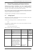
3 TRANSMITTER I/O CONNECTIONS
3.2 9 Pin Front Panel Connector
Function Signal Pins Specification
dc power +28Vdc(in)
0 Vdc
+5Vdc(out)
+12Vdc(out)
13, 25
1, 14
17
15
+24 to 32 Vdc
Common Voltage
Output for external Logic(100mA)
Output for an external relay(120mA)
Serial
Communications
SCLK
MOSI
CH_EN
PA_CS
SPARE_SEL
12
6
18
24
5
Serial Clock
Bi-directional Data Pin
Enables Channel Select Shift Register
Enables PA A/D chip
Spare Select (for future use)
600
Ω
/HiZ Line
Line1+
Line1-
8
19
Transformer Isolated Balanced 0dBm
Input
600
Ω
/HiZ Line
Line2+
Line2-
10
22
Transformer Isolated Balanced 0dBm
Input
Direct PTT input 11 Ground to key PTT
T/R Relay driver
output
23 Open collector, 250mA /12V
Sub-Audible Tone
Input
Tone+
Tone-
9
21
>10k
Ω
, dc coupled
Table 3: Pin connections and explanations for the main 25-pin, D connector.
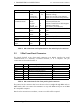
3.2 9 Pin Front Panel Connector
The female D-shell, 9 pin, front panel connector is an RS232 interface for serial
communications to a terminal, a terminal emulator, or to a computer. The pin
connections are described in table 4.
Function Pins Specification Pin name on IBM PC
TXD 2 Transmit Data (Output) RxD
RXD 3 Receive Data (Input) TxD
RTS 8 Request To Send (Output) CTS
CTS 7 Clear To Send (Input) RTS
DTR 6 Data Terminal Ready(Output) DSR
DSR 1 Data Set Ready (Input) DCD
GND 5 GND GND
Table 4: Pin connections for the front panel 9 pin D connector.
The pinout for the connector has been chosen so that a straight-through BD9 male to
DB9 female cable can connect the transmitter to any male DB9 serial port on an IBM
PC compatible computer.
Note that for connection to a modem, a cross-over cable will be required.