
Operation and Maintenance Manual


RF Technology T220 Page 9
4 CHANNEL AND TONE FREQUENCY PROGRAMMING
TecHelp can be supplied by your dealer, distributor or by contacting RF Technology
directly.
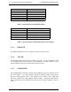
Function Signal Pins Specification
dc power +12 Vdc
-12 Vdc
1, 14
13, 25
+11.4 to 16 Vdc
Channel Select 1
2
4
8
10
20
40
80
21
9
22
10
23
11
24
12
BCD Coded
0 = Open Circuit
or 0 Vdc
1 = +5 to +16 Vdc
RS232 Data In
Out
15
2
Test and Programming use
9600, 8 data 2 stop bits
600
Ω
Line
High
Low
20
6
Transformer Isolated
Balanced 0dBm Output
150
Ω
/ Hybrid
7
19
Direct PTT input 3 Ground to key PTT
T/R Relay driver output 16 Open collector, 250m /30V
Sub-Audible Tone Input + 5
>10k
Ω
, AC coupled
18 (1-250Hz)
High-Z Audio Input + 4
>10k
Ω
, AC coupled
- 17 (10Hz-3kHz)
External ALC input 8 <0.5V/1mA to obtain
>30dB attenuation, O/C
for maximum power
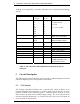
Table 3: Pin connections and explanations for the main 25-pin, D
connector.
5 Circuit Description
The following descriptions should be read as an aid to understanding the block and
schematic diagrams given in the appendix of this manual.
5.1 VCO Section
The Voltage Controlled Oscillator uses a junction FET which oscillates at the
required transmitter output frequency. A varactor diode is used by the PLL circuit to
keep the oscillator on the desired frequency. Transistor Q20 is used as an active
filter to reduce the noise on the oscillator supply voltage. The VCO is keyed ON by
the microcontroller through Q10. It is keyed ON when any of the PTT inputs are
active and OFF at all other times.