
Operation and Maintenance Manual


Page 8 RF Technology T220
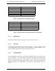
2.5 JP7: Audio Response 4 CHANNEL AND TONE FREQUENCY PROGRAMMING
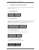
2.5 JP7: Audio Response
Condition Position
750 uSec. pre-emphasis 1-2 *
Flat response 2-3
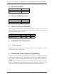
2.6 JP8: Sub-audible Tone Source
Condition Position
Internal CTCSS 1-2, 4-5 *
External input 2-3, 5-6
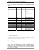
2.7 JP9/10/11: dc Loop Configuration
These settings are only relevant when the PTT signal is to be used across the same
wires as the audio. Refer to setting of JP3. They control the levels and connection
into the audio balanced line circuitry.
Condition JP9 JP10 JP11
Current Loop Input ON OFF OFF *
12Vd Loop source OFF ON ON
3 Transmitter I/O Connections
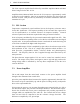
3.1 25 Pin Connector
The D-shell 25 pin connector is the main interface to the transmitter. The pin
connections are described in table 3.
4. Channel and Tone Frequency Programming
Channel and tone frequency programming is most easily accomplished with RF
Technology TecHelp software. This software can be run on an IBM compatible PC
and provides a number of additional useful facilities. DOS and 32-bit versions are
available.
TecHelp allows setting of the adaptive noise squelch threshold, provides a simple
means of calibrating the forward and reverse power detectors, setting the power
alarm preset levels, and enabling transmitter hang time and timeout time limits.