
Data Sheet

LAMBDA62 LoRa Transceiver
DS-LAMBDA62-6
Page 6
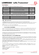
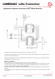
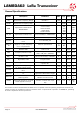
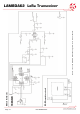
Application schematic Interfacing a PIC
TM
Micro Controller
The above schematic shows an easy interface to a PIC Microcontroller
This is the same application circuit that we used for range testing (please see our range test infor-
mation later in the document).
We also have application source code available for download on our website. This configures the RF
LoRa Module for maximum range.
Walk Test application
Also available is the source code used to carry out a simple range test.
In order to use this two application boards are required, one acts as a beacon transmitter, the oth-
er as the beacon receiver. The TX board will illuminate the GREEN LED when transmitting and the
Receiver will illuminate the RED LED when RECEIVING
The Transmitter board transmits an RF beacon every second (Green LED flashes to indicate trans-
mission).
This enables a one man range test, by placing either board in a fixed location and monitoring the bea-
con signals.
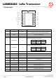
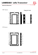
ANT
GND
+3.3V
RX_Switch
TX_Switch
BUSY
DIO1
DIO2
NSEL
SDI
SDO
SCLK
RESET
N/C
N/C
DIO3