
Data Sheet
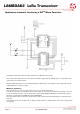

LAMBDA62 LoRa Transceiver
DS-LAMBDA62-6
Page 11
Range Test Notes
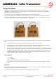
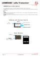
Transmitter and Receiver boards were built using simple Vero board and a PIC microcontroller
(16F886). The transmitter sent a beacon signal at 1 second intervals. The receiver acknowledges
this signal back to the transmitter.
A simple piece of wire was used as antenna for both transmitter and receiver.
This test was designed to represent a real life application. It is often difficult to design an applica-
tion with all RF features to an optimum potential i.e. the antenna was not 100% ideal as there was
no antenna ground plane, and the motherboard was rudimentary,
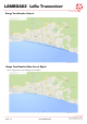
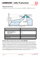
Our Range Testing was conducted on Brighton to Shoreham Seafront providing an open Line of Sight
Test.
1. The Transmitter was mounted on a plastic wheelie bin 4ft from the ground.
2. The Receiver was carried on the dashboard of a vehicle ( 5ft above ground) along the seafront.
Line of sight was not achieved until the receiver was at least 9km distance
3. As the receiver travelled away from the transmitter Line of sight was lost . A Reliable signal was
observed to about 3K range, thereafter the signal became intermittent. When the Transmitter
and Receiver regained Line of sight a reliable signal was again observed. This continued for the
available distance (about 12KM) at which point the terrain prevented further testing. At the
longest available range the signal was 100% reliable.
Test conditions
- T
A
= +25 °C
- V
DD
= +3.3 Vdc
- Dry, Broken Sunshine, Relative Humidity 45%
RF input and output levels can typically be achieved at the antenna port after filtering compo-
nents.
Conclusion
The product performed as expected. Unfortunately we ran out of land to test a LOS beyond 12Km ,so
the maximum range is further than tested here.
It is also clear that the product performs considerably better when in LOS.