
User's Manual

9
RF-Smart – User Manual Rev 1.1 – 12/11/2019
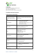
• Power Supply current rating: max. 2A @12V (if USB is used, use 3A Power supply)
• Power Supply ripple: max. 120mV
• Input current in idle mode: 20mA @ 12V
• Input average current in communication mode: 100mA @ 12V
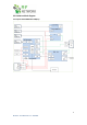
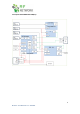
3.3 SMA CONNECTORS AND LEDs
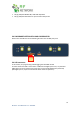
3.3.1 SMA Antennas connection
The RF-Gate Terminal uses SMA CONNECTORS for ANTENNAS.
RF Antenna: In RF 433Mhz use the 433Mhz ANTENNA with 2dB gain or more.
In RF 2.4Ghz use the 2.4Ghz ANTENNA with 2dB gain or more.
CELLULAR Antenna 4 band 3G ANTENNA with 2.5dB gain.
GPS/RF2 Antenna ACTIVE GPS ANTENNA with 25-28dB gain. (in RFN-SMART915-4NQ-
x0z, RFN-SMART433-4NQ-x0z is used for cellular Antenna diversity)
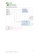
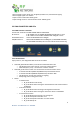
3.3.2 LED indications
Upon power on, the designated LEDs should act as follows
• CELLULAR_B LED Modem Status, when On the Cellular Modem is ON
o Fast blinks (around 2 per second) - search for cellular network
o Slow blink (every 2 sec) - connected to a cellular network
• CELLULAR_A LED turns on when it is connected to the communication server
o 2 seconds Slow Blink (200ms ON/1800ms OFF) Low Network Search
o 2 seconds Slow Blink (1800ms ON/200ms OFF) modem in IDLE
o Fast blink 4 per second, Data Transfer is Ongoing
o Always High, Voice calling (not in USE)
• RF LED
o In STAR versions
▪ RF_B LED blinks on RF activity
▪ RF_A LED blinks when moving the data between the RF and the Smart or
3G Module
o In Receiver versions
▪ RF_B LED blinks when receiving an RF tag data transmission
▪ RF_A LED blinks when moving the data to the Smart or 3G Module
o In Coordinator Versions
▪ RF_B LED blinks means the RF is not configured
▪ RF_B LED steady ON coordinator is on
▪ RF_B LED steady ON coordinator is in Boot Loader
▪ RF_A LED always off