
User's Manual

12
RF-Smart – User Manual Rev 1.1 – 12/11/2019
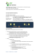
3.6 AUX A Interface
The AUX interface provides via Male 6-pole plug connector, the following options:
• Power control pin – To be use with internal PMW for 125khz transmitter
• GPS PPS – direct output of PPS for Time stamp
• TX AUX and RX AUX of the Modem
• Ground pin, VIN pin to supply to external board (after input diode and spick suppressor)
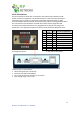
3.6 AUX B Interface
The AUX interface provides via Male 6-pole plug connector, the following options:
• 2 digital inputs opto couplers, input 0-55vdc.
• 2 outputs opto couplers, drive up to 100ma, external diode needed when driving a relay.
• 1 ADC (10 bit) input 0-55v.
• 1 Ground pin.
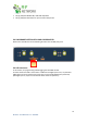
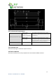
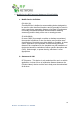
3 2 1
6 5 4
Pin assignment
1. POWER CONTROL / GPO
2. GPS PPS/Analog Input
3. VIN
4. RX AUX MODEM/I2C
5. TX AUX MODEM/I2C
6. GND
Male 6-pole plug.
To use with MOLEX MICRO FIT
PART NUMBER 43025-0600.
3 2 1
6 5 4
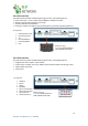
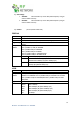
4 3 2 1
5 6 7 8
Pin assignment
1. POWER 4V
2. RELAY A
3. RELAY B
4. GND MAIN
5. INPUT A OPTOCOUPLER
6. INPUT B OPTOCOUPLER
7. OPEN COLLECTOR
8. GND OPTOCOUPLER
Male 8-pole plug.
To use with MOLEX MICRO FIT
PART NUMBER 43025-0800.
4 3 2 1
5 6 7
8