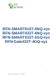
RFN-SMART915T-4NQ-xyz RFN-SMART433T-4NQ-xyz RFN-SMART915T-3GQ-xyz RFN-Gate433T-4GQ-xyz 1 RF-Smart – User Manual Rev 1.
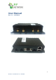
User Manual Rev. 1.1 – 12/11/2019 Front View Back View 2 RF-Smart – User Manual Rev 1.
1. Overview The RF-Gate is a complete RF Terminal solution for RF 433/915 Mhz applications. Based on Quectel Cellular modems and CC1310 radio. 2. Hardware Interface Description 2.
2.1.
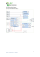
2.2 Hardware block diagram 2.2.1 Option: RFN-SMART915T-4NQ-xyz 5 RF-Smart – User Manual Rev 1.
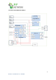
2.2.2 Option: RFN-SMART433T-4NQ-xyz 6 RF-Smart – User Manual Rev 1.
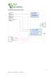
2.2.3 Option: RFN-GATE433T-4GQ-xyz 7 RF-Smart – User Manual Rev 1.
3. Interface description 3.1 Molex 4 pin connector – Power connector 3.1.1 Power Supply The power supply of the RF-Gate Terminal requires a single voltage source of POWER 6V-55V capable of providing a peak during an active transmission. The RF-Gate Terminal is protected against supply voltage reversal. An internal fuse 1.1A 60V ensures an electrical safety according to EN60950-1. This fuse is not removable. A fast blow fuse of 0.8A is necessary for 24V power supply system (for vehicles).
• Power Supply current rating: max. 2A @12V (if USB is used, use 3A Power supply) • Power Supply ripple: max. 120mV • Input current in idle mode: 20mA @ 12V • Input average current in communication mode: 100mA @ 12V 3.3 SMA CONNECTORS AND LEDs 3.3.1 SMA Antennas connection The RF-Gate Terminal uses SMA CONNECTORS for ANTENNAS. RF Antenna: In RF 433Mhz use the 433Mhz ANTENNA with 2dB gain or more. In RF 2.4Ghz use the 2.4Ghz ANTENNA with 2dB gain or more. CELLULAR Antenna 4 band 3G ANTENNA with 2.5dB gain.
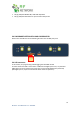
• • RF2_B (GPS) LED SMART TBD, USED SW dependent RF2_A (GPS) LED GPS blinks one per seconds if GPS present 3.4 SIM DRAWER OPTION CELLULAR COORDINATOR Please insert the SIM card on the following direction into the SIM push-push. 3.
3.5 RS-232 Interface The serial interface of the RF-Gate is intended for the communication between the RF module and the host application. This RS-232 interface is a data and control interface for transmitting data. It accepts, AT commands and provides multiplexed channels. EMC immunity complies with the vehicular environment requirements according to EN 301 489-7.
3.6 AUX A Interface The AUX interface provides via Male 6-pole plug connector, the following options: • Power control pin – To be use with internal PMW for 125khz transmitter • GPS PPS – direct output of PPS for Time stamp • TX AUX and RX AUX of the Modem • Ground pin, VIN pin to supply to external board (after input diode and spick suppressor) 6 5 4 Pin assignment 1. 2. 3. 4. 5. 6.
3.7 ETHERNET Interface The ETHERNET interface provides via RJ45 connector. 3.7 USB Type A Interface General propose Type A USB connector (max current supply 500mA fuse protected) (Managed by Linux, required user SW and device drivers to operate it) 4. Mechanical Characteristics 4.1 General mechanical description Weight 180g Dimensions (max) L x W x H 147mm x 71.5mm x 34mm Case material Aluminum 13 RF-Smart – User Manual Rev 1.
4.2 Environmental requirements -20°C to +55°C -4°F to 131°F ambient temperature The module is fully functional (*) in all the temperature range and it fully meets the ETSI specifications. -30°C to +70°C -22°F to 158°F The module is fully functional (*) in all the temperature range. Temperatures outside of the range –20°C to +55°C (-4°F to 131°F) might slightly deviate from ETSI specifications.
1) Short Range a. 433 MHZ FSK modulation up to 10 dbm (emitted power) using an external 3dbm antenna) b. 915 MHZ FSK modulation up to 14 dbm (emitted power) using an external 3dbm antenna) 2) Cellular (From Quectel Datasheets) EG95-NA LTE FDD WCDMA Carrier Regulatory Output Power Data B2/B4/B5/B12/B13 B2/B4/B5 Verizon/ AT&T/ T-Mobile/ Telus/ U.S.
BG96 LTE FDD LTE TDD EGPRS Output Power Approvals Data GPS Cat M1/Cat NB1 B1/B2/B3/B4/B5/B8/B12/B13/B18/B19/B20/B26/B28 B39 (For Cat M1 Only) 850/900/1800/1900MHz 23dBm GCF/Deutsche Telekom (Europe) FCC/PTCRB/Verizon/AT&T/TMobile*/Sprint* (North America) RCM/Telstra (Australia) Telefonica* (Spain) IFETEL (Mexico) IC/BELL*/Telus (Canada) JATE/TELEC/KDDI/SoftBank* (Japan) KC*/SKT* (Korea) IMDA (Singapore) CCC (China) Cat M1: 375Kbps (DL), Max. 375Kbps (UL) Max. Max. 32Kbps (DL), Max.
Class B information Note: This equipment has been tested and found to comply with the limits for a Class B digital device, pursuant to Part 15 of the FCC rules. These limits are designed to provide reasonable protection against harmful interference in a residential installation. This equipment generates, uses and can radiate radio frequency energy and, if not installed and used in accordance with the instructions, may cause harmful interference to radio communications.
1. Mobile Device RF Exposure Statement (If Applicable): a. Mobile Device definition: (§2.1091) (b) A mobile device is defined as a transmitting device designed to be used in other than fixed locations and to generally be used in such a way that a separation distance of at least 20 centimeters is normally maintained between the transmitter’s radiating structure(s) and the body of the user or nearby persons. §2.