
User guide


RF Mogul Indoor Unit User Guide
11
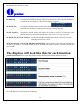
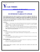
WIRING DIAGRAM
To Satellite Receiver
To Antenna
12 VDC Input
Ignition Stow
and
12 VDC Input
(This Port is
Optional)
Control Cable
Connection
Dip Switches
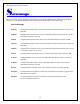
CONTROLLER CABLE CONNECTOR
(Green Connector)
Pin Color How Used Where Used
P1 = Violet
Limit Sensor
EL Up
P2 = Dk Blue
Limit Sensor
AZ
P3 = Green
Limit Sensor
EL Down
P4 = Gray
Encoder
SK
P5 = Yellow
Encoder
AZ
P6 = Brown
Encoder
EL
P7 = Black
Ground GND
P8 = Red VCC
P9 = White
Power
AZ-B
P10 = Pink
Power
AZ-A
P11 = Lt Blue
Power
EL-B
P12 = Orange
Power
EL-A
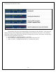
IGNITION STOW
(OPTIONAL)
P1 = To Positive side of Battery 12
VDC
P2 = To + 12 VDC side of car
ignition
P3 = To Ground of Battery
P4 = To Ground of Battery
2+
1+
4- 3-
Connections:
• P1 to the side of the car ignition and
• P2 to the +side of your battery and
• P3/P4 are connected to the negative
side of the battery
When you turn your ignition key ON,
your dish will automatically return to
the STOWED position which is the
travel position when wired using this
plug
.