
User guide


The Eagle Manual
11
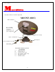
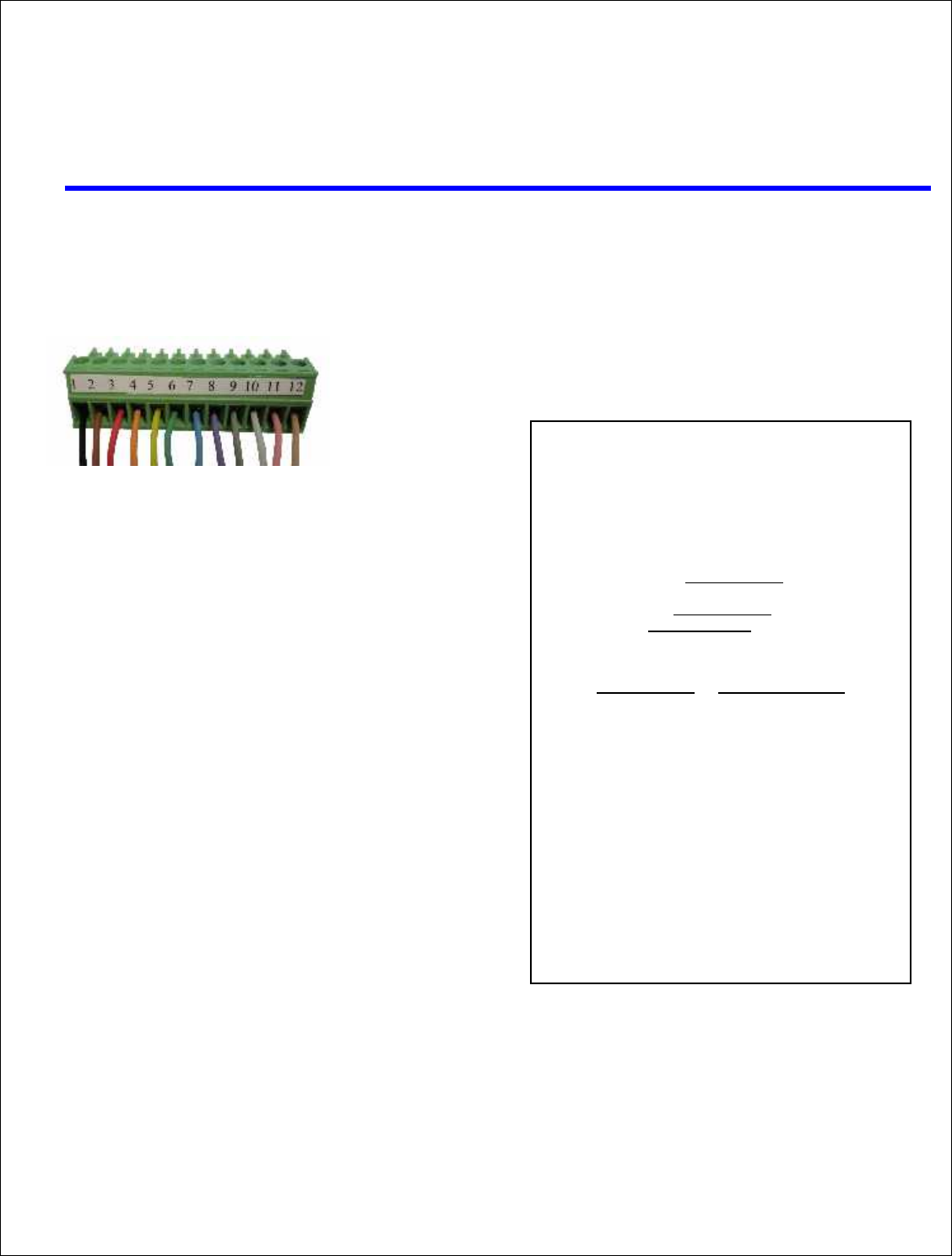
Connector Wiring Diagram
Wiring the
12 Pin Controller Connector
Pin Color How Used Where
Used
1 = BLACK Motor -Azimuth
2 = BROWN Motor +Azimuth
3 = RED Motor -Elevation
4 = ORANGE Motor +Elevation
5 = YELLOW Motor - Skew
6 = GREEN Motor +Skew
7 = BLUE Count Azimuth
8 = VIOLET Count Elevation
9 = GRAY Count Skew
10 = WHITE Ground
11 = PINK 12 Volts DC
12 = TAN GPS TXD
RAISING THE ODU
USING A 12 VDC SOURCE
TO RAISE THE MOUNT WITH
A BATTERY
Touch the following wires from the control cable directly to a
drill battery or any 12 VDC source and it will result in movement
of the ODU. To reverse the direction, reverse the wires to your
battery.
ELEVATION Red and Orange will raise and lower
the mount
AZIMUTH Black and Brown will rotate the dish
SKEW Yellow and Green will tilt dish.
Wire Color Wire Function
BLACK +AZ
BROWN -AZ
RED +EL
ORANGE -EL
YELLOW - SKEW
GREEN +SKEW