
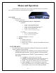
Specifications
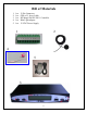

8
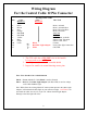
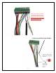
Wiring Diagram
For the Control Cable 12 Pin Connector
Wiring Color Code
Pin Color Color How Used
MotoSAT RF Mogul
1. Black Motor, Azimuth
2. Brown Motor, Azimuth/Skew
3. Red Motor, Elevation/Skew
4. Orange Motor, Elevation
5. Not Used Not Used
6. Not Used Not Used
7. Yellow Sensor Count, Azimuth
8. Blue Sensor Count, Elevation
9. Purple Sensor Count, Skew
10. Green Black Ground
11. Red /Blue Light Adapter Power, Blue light Connection
12.
White GPS TXD
Note: Pins 10 and 11 have a dual function
Pin 10 - Green (MotoSAT Cable) Black is used as Ground.
Pin 11 - Red (for GPS) Blue Light Adapter (for Blue LED) is used as voltage
to the GPS and Blue Light.
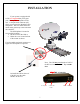
Note: White from the existing MotoSAT
control cable spliced to the "Blue Light
Adapter" will maintain the blue light on your reflector at night. CAUTION---do
not attach the white wire directly to pin #11 without the blue light adapter.
Damage to the blue light will occur.
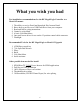
1. The GPS cable has a YELLOW wire in the bundle.
It is not used so cut it OFF.
2. Carefully cut and remove all stranded shield
3. Inspect for small wire strand shorting across pins.