
Users Manual


6
Operating and installation instructions RF-KIT Power Amplifier RF2K-S
3.2 Control elements and connections
1 Power switch O n / O ( 1 ) (main switch)
This rocker switch switches the device on / o .
2 Touch screen - GUI
This Touch screen controls the device in all operating states.
Also you receive context-related information about the operating
status of the device.
3 ANT 3
50 Ω antenna socket SO-239 (PL-259)
4 ANT 4
50 Ω antenna socket SO-239 (PL-259)
5 ANT 2
50 Ω antenna socket SO-239 (PL-259)
6 ANT 1
50 Ω antenna socket SO-239 (PL-259)
When device is switched o , ANT 1 (6) is looped through.
7 PTT
RCA connector for transmit/receive switching
At the center contact (+) of the connector PTT (7) +5 V are
present.
8 Power On Extern
RCA connector for remote control: The device can be switched on re-
motely by applying + 12V DC (at least 10 V, max 15 V!) to the center
contact. The power switch O n / O ( 1 ) must be switched o (“0“).
When DC voltage drops, the PA switches o .
9 Power jack
A plug for this power socket is included and can be wired to the user
supplied power cord capable of 16 Amps, that meets their countries
power plug requirement.
10 Fuse - automatic circuit breaker 16 A
If this automatic circuit breaker triggers several times in succession,
this usually has a valid reason!
WARNING!
Do not open the device by yourself, contact the manu-
facturer!
11 Ground connector
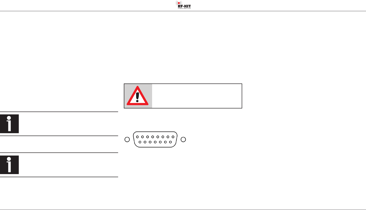
12 Multifunction connector DB-15
1
9
8
15
(Plugview)
DB-15 Connector Pin Assignments:
1 - In A Spare
2 - In B Spare
3 - In C Spare
4 - In D Spare
5 - Out A BCD band data output
(Transistor output, max. 15 V / 50 mA from external)
6 - Out B BCD band data output
(Transistor output, max. 15 V / 50 mA from external)
7 - Out C BCD band data output
(Transistor output, max. 15 V / 50 mA from external)
8 - Out D BCD band data output
(Transistor output, max. 15 V / 50 mA from external)
9 - TKEY Output / input for tuner control (available soon)
10 - TSTR Input for tuner control (available soon)
11 - RS232 TX -
12 - RS232 RX -
13 - GND -
14 - GND -
15 - OUT 15 V Max. 500 mA if device is switched on; can be used for
external controls (e.g., remote control relay control).
13 RJ45 LAN Connector
Here you can connect your RF2K-S to your home network for remote
control by LAN-cable.
Note: Alternatively you can use the build-in Wi-Fi to connect the
RF2K-S to your local Wi-Fi network.
14 Cooling fan
The high-performance fan is temperature-controlled and ensures
reliable cooling of the power electronics with minimal noise, even
during maximum continuous load (contest operation!).
15 CAT USB - USB 2.0 connector “CAT“
Band data import / export between exciter and PA.
16 -55 dB output
SMA connector for adaptive predistortion of the exciter signal along
with SDR transceivers.
17 TRX - 50 Ω SO 239 connector
Input exciter (transceiver) signal.