
Users Manual


14
Operating and installation instructions RF-KIT Power Amplifier RF2K-S
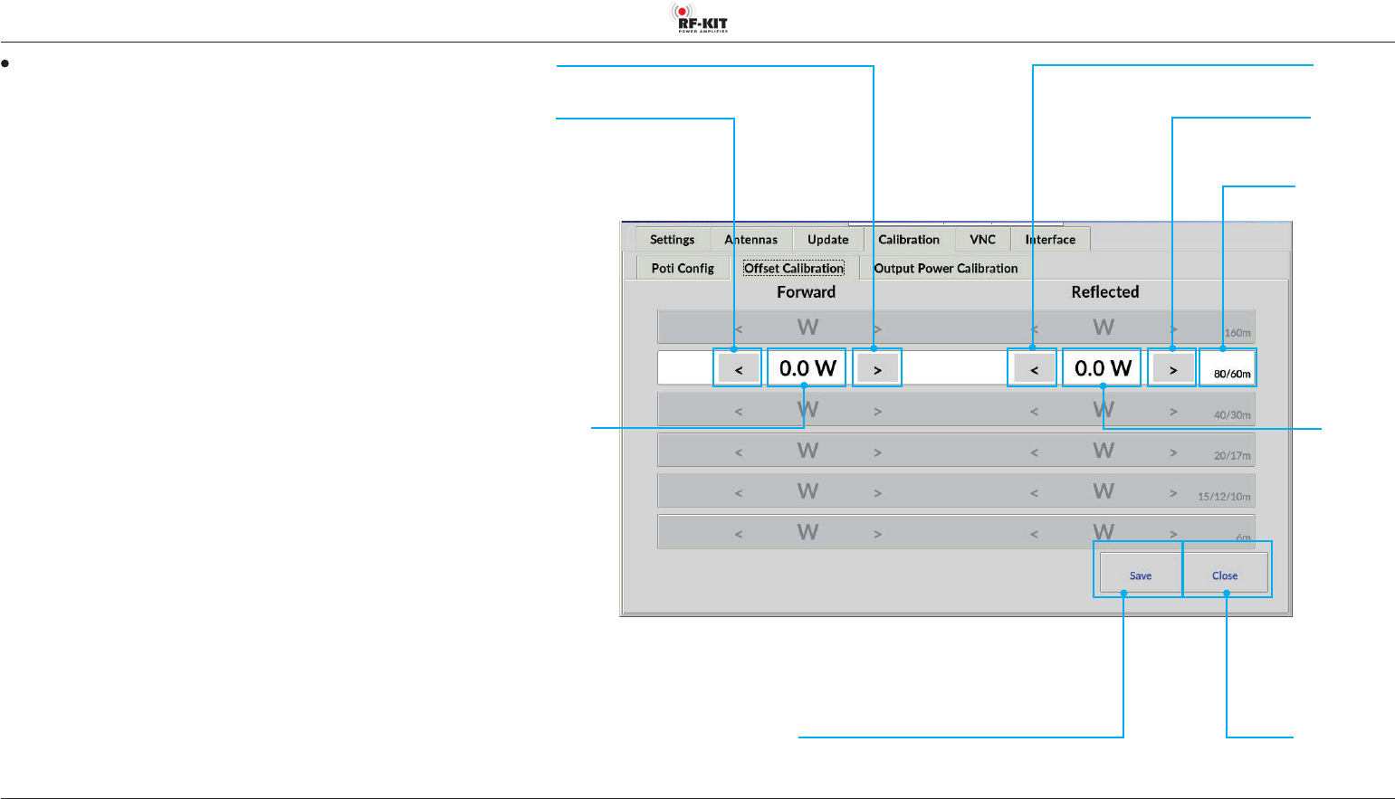
Oset Calibration
The unavoidable frequency-dependent deviations of the linearity of the di-
rectional coupler used for internal power measurement can be minimized
for each bandpass range.
The adjustment should be carried out at an output power of 1 kW.
Use your preferred reference wattmeter for the adjustment.
Selection of the bandpass range is done automatically during transmission.
The detected band is highlighted.
► Adjust the internal power display by pressing the buttons > (increase
value) respectively < (decrease value).
Brief actuation changes the value in the indication area Forward by 0.1 W.
Longer actuation changes the value continuously.
► Press the switching area Save to store the settings.
► Repeat this procedure for each bandpass range to be adjusted.
Indication area Band
Switching area <
(decrease value)
Switching area >
(increase value)
Indication area
Reected
Indication area Forward
Switching area >
(increase value)
Switching area <
(decrease value)
Switching area Close
Touching this switching area closes the user menu;
subsequently the main screen will be displayed
Switching area Save
Touching this switching area
stores the settings