Configuration Utility User Manual pcProx® Plus, pcProx® Enroll & Wiegand Converter ©2015 RF IDeas Configu ration Utility User Manual 99009010 Rev B2 Page |1
Thank You! Congratulations on the purchase of your pcProx® Enroll, pcProx® Plus, or Wiegand device(s). RF IDeas hopes you enjoy using the readers as much as we enjoyed creating and developing them. Configuration is easy, so you will be able to quickly take advantage of a more secure environment in your business, school, or organization. Please call our Sales department if you have any questions or are interested in our OEM and Independent Developer’s programs.
Glossary of Terms Terms ASCII Contactless FAC OEM pcProx Definitions The American Standard Code for Information Interchange codes represent text in computers, communications equipment, and other devices that use text. The high frequency 13.56 MHz smart card technology. Facility Access Code. The card and badge reader without case. Available in self-contained modules for easy system integration. The RF IDeas brand name given to all 125 kHz proximity and 13.56 MHz contactless smart card readers.
Contents Device Menu ............................................................ 13 Navigation Menu ...................................................... 20 View Menu ............................................................... 20 Glossary of Terms .............................................. iii Card Analyzer Menu ................................................ 22 Information Symbols .......................................... iii Chapter 1. 1.1 The Basics ......................................
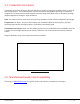
Chapter 1. The Basics 1.1 Wireless Identification Overview pcProx® Activated Identification Employers are more security conscious than ever. More buildings, machines, systems, and applications require identification information to gain access. RF IDeas devices allow the building access cards to be used as a digital identifier throughout the workplace.
Image 1: Card Reader Overview 1.
1.4 Credential Form Factors Credentials are inactive electronic devices that rely on readers to supply the required power for start-up and communication. The credential itself, consists of antennas that produce proximity or contactless frequencies. Proximity and contactless smart card technology cards allow users to effortlessly manage multiple applications through a single credential. Data: The data on access cards are a string of binary numbers set with a fixed configuration and length.
1.6 Reader Configuration Purposes The method of encoding data on a card and transmitting data to the reader differs accordingly in each technology involved. The reader itself is not aware of the makeup of the card data format or access privileges for the cardholder. This information is only accessible through the configuration process of the reader utilizing the supplied software.
Chapter 2. Hardware 2.1 What’s in Your Part Number? All RF IDeas reader part numbers follow a distinct system of categorization to allow for an ease of differentiation between products. Below is the basic part number scheme: Image 4: Reader Part Number Scheme Device Type: The device type distinguishes between Standard Reader (RDR), Wiegand Converter (OEM), Converter (C), Kit (KT), or Mag Stripe Reader (MS3).
Version: The version refers to the selection of either our Standard (A) or Custom builds. (For more on Custom builds, call our Sales department at (866) 439 - 4884). Housing Color: The color category simply allows for the selection of either our Black (K), Pearl (P), White (W), or Gray (G) housings. (Colors are not available in all housings.) Interface: This option specifies the type of connection for the reader.
Output Output includes: Image 6: Output Types 2.3 USB Readers and Wiegand Converters The pcProx USB keystroke device operates in two primary modes: 1. USB keyboard. It reads the card data and sends it as keystrokes as if the user typed the ID data on a keyboard. 2. Under the application programmer interface (API) defined in the pcProx SDK. When it reads card data, the active application receives the entire card data. T The pcProx ExpressCard operates as a USB reader. 2.
2.5 Minimum System Requirements Components Hardware Memory Disk I/O Operating System Minimum System Requirements Pentium Class PC 64 MB RAM 650 MB Hard Disk Space 1 available RS-232 or USB Port Any operating system that supports a USB keyboard including Microsoft Windows 2000®, XP®, Vista®, 7®, 8®, 8.1®, 8.2®, Server 2003®, and Server 2008®. The software does not perform any data validation checking. The data must be known before it is read to verify its validity. 2.
2.8 Beeper To allow the device to produce a beep when a credential is detected by the reader. The LED and Beeper are configurable through the utility software.
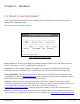
Chapter 3. Software 3.1 pcProx Configuration Utility The pcProx Configuration Utility provides users with the ability to configure their pcProx Enroll, pcProx Plus, or Wiegand devices to meet their needs. Through the configuration process, desired credential data output and access privileges for cardholders can be established.
3.3 Menu Toolbar Image 8: Menu Toolbar The Menu toolbar contains all the basic configuration options for the utility. File Menu Image 9: File Overview The file menu entry will only be enabled for USB readers, and not for serial readers. The File menu lists the options for Opening .hwg and saving .hwg files. For pcProx Plus reader, all configurations need to be written to the file. The configuration numbers should be labelled as 1 through N to match the pcProx Config app.
What is libusb? “libusb-win32” is a port of the USB library. The library allows user space applications to access many USB devices on Windows. Save USB device hex raw data to (SDK) file…: A USB raw feature report dump to an ASCII text file. Save USB device hex raw data to (SDK) file option is enabled for USB readers, not for serial and NTWCC readers. All bytes are displayed as upper case hex digits, with one space between the hex bytes. Exit: Exits out of the entire utility.
Connect to USB: Connects to current specified reader through USB. Connect to Serial: Connects to current specified reader through serial. Connect to Ethernet TCP/IP: Connects to current specified reader through Ethernet TCP/IP. Why use the Connect to feature? The Connect to feature allows the utility to connect to a device through the specified port upon selection. This is especially helpful when users are switching out and changing devices with different connections.
For more information on the Write Settings option, see 3.4 Icon Toolbar under the Write Settings/Write Active section. For more information on the Clone selected reader configuration to other devices option, refer to the next page. pcProx Plus - 2 Configuration Reader Image 11: Device Menu for pcProx Plus -2 Configuration Readers • • • Reset to Defaults: Resets all configuration parameters to defaults.
The cloning feature clones the current device configuration settings to other devices. Functions Only update readers within the LUID range Descriptions Check to filter which devices will be cloned. Uncheck to clone all devices. Minimum LUID Minimum LUID value to filter a range of devices to be cloned. Default is 0x0000. Maximum LUID Maximum LUID value to filter which devices will be cloned. Default is 0xFFFF. Write LUID Check to write a new LUID to the device after cloning.
Image 13: Clone Configuration Reader Dialogue Box The range displayed in the Minimum LUID and Maximum LUID fields will only come in effect when the “Only update readers within the LUID range” option is selected. Starting LUID and Increment by fields will be written in the new readers only when the Write LUID field is checked.
4. Disconnect the reader. Image 14: Reader Disconnected You have approximately 18 seconds after disconnecting the reader to connect the readers to be cloned.
If there are multiple readers that will be connected to undergo the cloning process, it is suggested that a hub be used for the readers to be cloned. See the following image. Image 15: Reader Disconnected 5. Connect the reader(s) that will be undergoing the cloning process. Image 16: Connecting Other Readers More than one reader can be configured. Configuration must be done one reader at a time.
Image 17: Connecting Second Reader Once the configuration process has finished, the below message will be displayed. Image 18: Configuration Finished 6. Click the “Close” button to close the “Clone Reader Configuration” dialogue box. 7. Click the “Connect” button in the “Configuration Utility” to check the new cloned configuration of the connected readers.
Navigation Menu The Navigation menu gives users the ability to navigate in and out of the utility tabs through the use of hot keys. This menu lists the hot key commands for the tabs as seen on the Standard Configuration Area (an explanation of each tab can be found in the Standard Configuration Area section of this manual). For example, pressing the F5 key on the keyboard will open the Data Format sub-tab: Image19:Navigation Menu Hot Keys A Test App hot key command is also available in this list.
Image 20: Pop-Up Warning Dialogue Example Show Confirm Dialogue: Menu option for displaying yes/no confirmation dialogues before certain utility operations are completed. For example, if the Show Confirm Dialogue option is selected, a confirmation dialogue window will appear when a user clicks to reset their device to factory defaults. If the Show Confirm Dialogue option is not selected, all utility operations will continue upon user selection without the need for confirmation.
Card Analyzer Menu The Card Analyzer makes it easy to learn and analyze a card in order to configure a reader. The Card Analyzer comes in handy especially when setting up a new reader system or issuing new cards. The Card Analyzer will quickly learn the card, then allow the reader to be configured based on the analysis of the card. The Card Analyzer also makes it easy to configure and write custom card IDs.
To begin, navigate to Card Analyzer from the menu on the utility. Image 21: Card Analyzer Menu The Card Analyzer utility supports pcProx® Plus RDR-80581AKU or RDR-80081AKU readers only. Detecting the Reader The Welcome screen provides a brief introduction, and provides the reader connection status. Image 22: Detecting the Reader Function Status Back Learn Card Exit Description The status may display the following: • “Reader not connected”. Ensure the reader is connected properly.
Learning Card After the reader is detected, proceed to Learning Card process. This is where the Card Analyzer will attempt to learn the type of card by scanning for matches. Each screen of the Card Analyzer also gives a general overview of the process, and the steps being performed in each phase of the utility. The first part is the scanning phase, where the application will scan the card for matches.
Every time the Start Scan button is pressed, the application scans for the Contactless 13.56 MHz, and Proximity 125 KHz Card Types. To learn a card: The application saves the current reader settings prior to scanning. They are restored if the user exits without writing the discovered settings. Click the “Start Scan” button. The “Pop-up Window” appears. Image 24: Starting the Scan The “Back” button is disabled and the “Auto Config” button is unavailable during scanning.
When prompted, place a card on the reader, click the “OK” button. Image 25: Placing the Card The analyzer will begin scanning the card for potential card type matches. Matches are displayed in the “Card Type” field. Image 26: Scanning Process “Start Scan” button will be unavailable during the scan process. User can use the “Halt Scan” button to stop the scan process.
After the scan is complete, the following message will be displayed: Image 27: Scanning Complete Select any card type to view the list of supporting readers. If no Card Type is detected, the application will display “Card not found: Please contact RF IDeas for additional support”. Image 28: Card Not Found Scenario To scan a new card, click the “Start Scan” button, and repeat the process.
To configure the reader, click the “Auto Config” button. Image 29: Starting the Auto Configuration Auto Config After Learn Card has determined the card type from the card scan, the reader can be configured to send the Card ID displayed in the Card ID status window. The utility displays the Card ID found based on the default reader settings. The user can highlight each listed Card Type and validate the Card ID number to the card.
It is not possible to jump directly to the “Auto Config” feature without first performing the “Learn Card” feature. Field/Button Description Contains the Card ID based on the defaults settings for the selected Card Card ID Type. When the user selects a “Card Type”, the application displays the Card ID Card Type based on the most popular default settings for the selected card type.
If you’re unable to locate the ID listed on the card, you can click the “Learn” button and try a new card, or press the “Analyze” button to find the card settings. By default, “Configuration #” is set to off prior to writing. After the card is removed from the reader, click the “OK” button to continue writing the configuration to the reader. Image 32: Pop-up Window for Removing the Card The Card Analyzer will then automatically begin writing the chosen configuration to the reader.
After configuring the reader with default settings, a message will appear in the status bar. Image 34: Writing Process Complete Analyze Card Configurations can be written in the Analyze Card section, much like the Auto Config section. This is a useful feature, especially if the card has a custom settings or doesn’t match the default ID. It’s also possible to analyze the reader settings for the selected Card Type. On-screen instructions are provided to add clarity.
Field/Button FAC ID Analyze Card Types Analyze Card ID Configuration # Write Learn Card Description Field to enter a Facility Access Code (FAC). Field to enter a card ID. Starts the card analyze function. The application will attempt to learn the settings for the selected Card Type. Displays learned Card Types. Each card type is selectable. Displays status to the user: “Card ID found”, or “Contact RF Ideas for additional support” if no results are found.
After writing the configurations to the reader, Press the “Exit” button (G) to stop the Card Analyzer and return to the configuration Utility. Image 36: Analyzing the Card Exiting It’s easy to exit the Card Analyzer at any time. If no configurations have been written, the reader will return to the original state. If configurations have been written during the “Auto Configuration” or “Analyze” processes, simply exit the Card Analyzer.
After exiting, the main pcProx Plus Configuration screen appears. Either continue with additional configuration settings or close the utility. Image 38: New Configuration in the Utility Help Menu The Help menu provides options for which users can seek out additional assistance using the utility and/or device. Read User Manual: Opens the pdf user manual that is bundled in the download with the configuration utility.
3.4 Icon Toolbar Image 39: Icon Toolbar The Icon Tool Bar contains the three most general configuration controls for the utility. These controls are also found in the Menu Toolbar under Connect (for connect and disconnect) and Device (for write settings and write active). Connect Image40:Connect Button Clicking the Connect icon button commands the utility to search for a device through all available port connections.
Image 41: Device List Output If an attempt to connect to a device is made and the utility does not detect a device through any of the available interface connections, a no devices found message will display in the utility’s status bar area, as shown in Image 24.
Image 42: Status Bar Disconnect Image 43: Disconnect Button Clicking the disconnect icon button, commands the utility to disconnect from all devices connected through any and all available port connections. Once the utility disconnects from all available device connections, the Device List pull-down menu and device model number are cleared from the Standard Configuration Area and the Output Test Area will turn from green to gray.
The status bar will display a Disconnected message, as shown in Image 26: Image44:Disconnected Message Write Settings/Write Active Image 45: Write Settings Button The Write Settings icon button prompts the utility to write the current defined configuration settings to the device. Since the writing options differ between a single configuration device and a two-configuration device (pcProx Plus), the Write Settings icon will change depending on whether a single or twoconfiguration device is connected.
3.5 pcProx Plus Configuration The pcProx Plus Configuration Area is only available to configure selections when a two configuration device (pcProx Plus) is connected to the utility. Image 47: pcProx Plus Configuration Area When a single configuration device is connected to the utility, the pcProx Plus Configuration area is greyed out (as seen above) and selections within this area are not possible, as shown in Image 29.
High Priority: Provides a pcProx Plus user the ability to give a certain configuration a higher priority than another. This is useful when the user has a population of cards consisting of a combination of 13.56 MHz/125kHz cards as well as single-technology cards, and one of those is preferred over the other. When the High priority feature is enabled, the reader will try to read that card type 10 times before switching to the other configuration. 3.
Serial devices may slow when scanning a wide port range. Ethernet (Local IP 10.10.10.65): Connects to an Ethernet reader at the given IP address and opens a TCP/IP on the given port. The first, second, third, and fourth byte of the TCP/IP address must be entered for the interface to connect to the reader. The IP port number will also be required. Port Option: Allows for changing the Internet socket port numbers. Ports below 1024 are for system use only.
Output Test Area Image 51: Output Test Area This is the test area for the keystrokes entered by the reader. On serial devices this displays the unsolicited serial port data. The Auto GetID box can be checked for the utility to poll the reader for a card ID every 500 milliseconds and displays the results directly under the checkbox, as seen in Image 34. Image 52: Auto GetID The Auto Focus box keeps the cursor in the test area box to capture the keystrokes output by the device.
Status Bar Image 53: Status Bar 3.7 Timing Tab Use this tab to configure the device’s card timing and USB keystroke timing. Card Data Hold Time: This option allows users to determine in millisecond’s how long they need to wait before the device is able to read the next card in line (which is also how long the LED will remain green after a card read). The timing options can range from 50 to 9950 min/max (50 milliseconds increments only) and the default is set to 1000.
Key Press Time: The length of time the key is held down. The minimum value is 0. The maximum is 640. The default is 20. Key Release Time: Enter the time delay between keystrokes. If set to 0, the reader will output as fast as possible. The minimum value is 0. The maximum is 640. The default is 20. Image 55: USB Keyboard Emulation Timing Key press time and Key release time are adjustable in increments and decrements of 4 milliseconds. 3.
Software Developer’s Kit Function Description Disable Keystrokes for SDK (Halt Keyboard Send) Check to disable keystroking. When keystroking or unsolicited (Halt Keyboard Send) serial out is disabled, all card data must be read via the SDK functions. LED The LED section allows users to control the LED light actions on the device to provide users info regarding the card data. Functions Auto Off Red Green Amber Descriptions Select this to make the device set the LED color.
Image 58: Beeper The number value input area to the right of the Long Beep(s) box is designated for the number of beeps to produce when the device is in use. OEM Converter Board Functions Descriptions Beeper On (Output Active Low) Relay On Check this to turn the device beeper on. Check this to turn on relay output on converter board. Image 59: OEM Converter Board Card ID Functions Descriptions GETID Click while scanning a card over the device. The ID displays under the button.
Image 60: GETID Data Display The Most Significant Byte is first – 79.
3.9 Format Tab Data Format Tab Image 63: Data Format Tab This tab provides users the ability to format how the data on a card will be keystroked out by the utility. Image 64: Data Characters Image 46 illustrates the various characters that can be displayed upon a card detection by a connected device.
The number portions of the diagram are values that are displayed from a card. The letter portions of the character diagram are values that are formatted by the user through the utility and are keystroked from the device. Wiegand to Keystroke Data Format Strip Leading and Trailing Bit Count: By altering the numbers in the leading and trailing bit count, users have the option to strip and discard bits from the card data. The leading and trailing bit counts can be set to range from 0 to 15.
AZERTY Keyboard Shift Lock: Displays the output as if it were being output from an AZERTY keyboard. FAC Extended Precision Math On: Check this to display the true representation of the number or if the card is over 32 bits. ID Extended Precision Math On: Interprets the ID data from a card to allow for the proper amount of bits to provide appropriate info. Reverse Wiegand Bytes: Reverses data in byte chunks (8 bits = 1 byte).
Only 3 pre and post delimiters total can be configured. If 3 pre-delimiters are set, no post delimiters can be set. Pre Data Delimiters (ABC): Select from 0 to 3 characters to display at the beginning of the card data. These characters are shared with the post string of characters. FAC/ID Delimiter (:): Select a character to display between and separate the FAC and ID data. Image 66: FAC/ID Delimiter Post Data Delimiters (XYZ): Select from 0 to 3 characters to keystroke to the end of the card data.
Delimiter Keyboard Image 67: Delimiter Keyboard The Delimiter Keyboard is used to select user defined delimiters (keys). Once opened users can: • Left Click: Selects desired delimiter (key). • Left Double Click: Selects desired key and auto insert (the Insert button will also insert the key). • Right Click: Toggles between keeping the left Shift on or off. The selected delimiter keys will highlight and appear in the top left corner that is initially labelled .
Special Keys - Sp1, Sp2, and Sp3 There are some additional measures that can be taken to make it more difficult for unauthorized users to reproduce passwords, such as, by adding additional keystroke characters to the card information that is difficult to reproduce, while configuring the data. These additional characters are labeled as Sp1, Sp2, and Sp3 on the delimiters Virtual Keyboard.
Image 69: Define Fields Functions Descriptions Define Fields Click to select the number of source bits to define the fields. The correct type must be selected to allow for all card bits to be manipulated. Enable Check to enable the highlighted field. This allows the delimiters to be output and the corresponding card field to be processed and output. All green fields are enabled. All red fields are disabled.
GetID Start Bit Bits Digits Up Down Click to display the binary bit pattern captured from the card. Enter a number to define the left most significant starting bit for the field. Enter the number of bits to add to the Start Bit to define the range of bits in the field. This is the number of digits that will display in a selected field. Click to move the highlighted field up one position. Click to move the highlighted field down one position.
Image 70: Output Example In the example Image 52, the Personal ID starts at bit 111, and is 50 bits long.The Bit Range is 111 .. 160 and the card bit pattern is highlighted. This output format is displayed in binary coded decimal with parity (BCD with parity). This is the 245 bit configuration. If any additional keystrokes were entered to precede the card data, click Clear to remove them.
Image 71: 31 Keystroke Limit In case of pcProx Plus reader with extended feature, each field has a 31 keystroke limit. This may be reduced because all the fields share 122 bytes of the extended device memory. GetID Click GetID and scan the card to display the output format of the FIPS 201 and proximity card and the interpretation display of the card data. Click GetID to define the fields to set up the device.
Click Clear to delete the red card data in the text field. A confirmation message will display. The Start Bit changes the actual location of the selected field on the binary bit pattern. Image 73: Start Bit Example The ‘????’ that display below the Number of bits field indicate the BCD parity is incorrect. Verify the correct field is selected. Change Fields Configuration Click on the appropriate field button and uncheck Enable to remove field data from being displayed.
Assign Preceding Keystrokes If Enable is checked for a field, specific keystrokes can be assigned to precede card data output. Image 75: Enable Field Example The Scan Code output for the key selected displays above the list of keys. Click Clear to remove all preceding keystrokes as appropriate.
Image 77: Single Keystroke Example Each single keystroke entered to precede card data equals 1 byte of memory for FIPS201 devices, and serial pcProx Plus devices with the extended feature. Image 78: Special Character Keystroke Example If any special character Left control, Left GUI, Left Alt, Right control, Right GUI, Right Alt, Right Shift except for ‘Left Shift’ is selected with a keystroke, this equals 2 bytes of memory for FIPS201 USB devices.
Every keystroke entered to precede card data equals 2 bytes of memory for pcProx Plus USB devices with extended feature. If all the keystrokes have been assigned to the fields, the following message displayed below will appear: Image 79: Key Stroke Memory Full Depending on the active document/window, additional functionality can be assigned to a field. For example, if the card data is read in Notepad, Print dialogue can be opened. Select the FAC field. Click the keyboard icon.
Image 81: Print Dialogue Box ©2015 RF IDeas Configuration Utility User Manual P a g e | 62
FIPS201 Reader Configuration To configure Reader for FIPS201 card: 1. Click “GetID” and present the card to the reader.
2. Define the fields to match the specific output. There are 6 predefined configurations for FIPS201 cards. Image 83: Define Fields Dialogue Box 3. Configure any additional fields as appropriate.
4. Save the configuration to memory.
Configuring the Reader in Extended Mode 1. Connect to the reader using the available communication port supported by your reader and press the “Connect” Button (A). 2. Select the Extended/Hashing radial button and press the “Write Active” button (C). 3. Select the “Extended” tab (D), all fields on this tab are active for the pcProx Plus with the Extended feature.
Determining the Card Size 1. Press “GETID” (A) and wait for the “GetActive ID” dialogue box to appear. 2. Place the curser in the dialogue box (B) and present the card to the reader. 3. The default field setting values will appear in the dialogue box (B) and automatically close. 4. Now the application is configured using the default settings determined by the card size.
Selecting the Bits to Use for the Facility Code (FAC) Field 1. In this example field 1 “FAC” is used as the field for our facility code. In the “Where” box, the “Start bit” (A) field is used to determine the facilitiy code start position. 2. The size or number of bits used for the facility code are determined by the “Number of bits” field (B). 3. The bit box (C) displays the selected bits in blue. 4. The blue data box (D) contains the value of the selected bits.
Selecting the Bits to Use for the Card ID Field 1. In this example field 2 “ID” (A) is used as the field for card ID. In the “Where” box, the “Start bit” (B) field is used to determine the ID start position. 2. The size or number of bits used for the ID are determined by the “Number of bits” field (C). 3. The bit box (D) displays the value of the selected bits in blue. 4. The blue data box (E) contains the value of the selected bits. 5.
Verify the Reader Settings 1. Open Notepad and place the curser inside the editor (A). 2. Present the card to the reader and verify the values match the selected bits for fields 1 and 2. Image 91: Verifying the Reader Settings Determining the Card Format It is important to be able to determine the format of the card data in order to locate the ID and FAC bits. Cards come in many bit formats. It is necessary to determine any Leading and Trailing parity bits and exactly how the ID and FAC are configured.
MSB LSB 00011011000111110011011011 001101100011111001101101 (FAC54) (ID15981) Enter the decimal number you believe is on the card into the Windows calculator and use the scientific mode to find the binary equivalent. In the example above, a FAC of 54 and ID of 15981 were known values. The leading parity bits are the most significant. The trailing parity bits are least significant. Hashing Tab Hashing tab is used to write two configurable 16-byte Hash Keys to the device's flash memory.
Function Key A Key B Enhance Security Definition First 16 byte hash key. Second 16 byte hash key. Enables security flag within device’s memory. Image 93: Hashing Code Values User can enter maximum 16 character string in one or both fields to create the new hashing key or keys. If user enters less than 16 characters, the string will be padded with null value. After successful write operation, the application will clear the text boxes.
The Enhance security feature enables the security flag within the reader’s memory. Entering the Hashing key or keys, checking the Enhance Security enable box, and pressing Write Active enables the Enhance Security feature. The user can enter keys or enable the security function separately. Image 95: Write Active Warning The Enhance security feature removes the Hashing keys if the user tries to reconfigure the reader after the security feature is enabled.
Chapter 4. Tips and Troubleshooting 4.1 Troubleshooting If the device is not working or the following error message is displayed: Image 96: No Device Connected 1. Check to be sure the device is connected to the USB or RS-232 port. When the workstation is on and no card is being read, the LED is red. A valid proximity card causes the LED to turn green, provided the configuration is not set to only read certain bit lengths. 2. Only one COM port application can own the RS-232 port at a time.
4.2 Precautions Do not mount the device directly on a metal surface. This could interfere with the RF signal and the operation of the device. The device may not recognize valid cards in the presence of high RF fields. If current readings are erratic, take the following step: Move the equipment from any known transmitters nearby. Contact Technical Support at (866) 439 - 4884 for more information. 4.
END-USER LICENSE AGREEMENT LICENSE AGREEMENT End-User License Agreement for RF IDeas™ SOFTWARE and HARDWARE - RF IDeas’ pcProx®, Proximity Activated Readers, Software Developer’s Kit, and Proximity Reader DLLs, and Protocol(s).
4. OEM COPYRIGHT. All title and copyrights in and to the PRODUCT (including but not limited to images, photographs, animations, video, audio, music, text and “applets,” incorporated into the PRODUCT), the accompanying printed materials, and any copies of the SOFTWARE PORTION OF THE PRODUCT, ar e owned by RF IDeas or its suppliers. The PRODUCT and SOFTWARE PORTION OF THE PRODUCT is protected by copyright laws and international treaty provisions.
Index Key Release Time · 44 A ASCII · 1, 7, 12 B Beep · 21 Beeper · 9 binary · 70, 71 C Card Compatibility · 3 Card Data Hold Time · 43 Change Fields Configuration · 58 Clear button · 42 Connectors · 6, 41 Continuous Read · 43 L LED · 45 Lock-Out Time · 43 Logical Unit ID · 45 LSB · 71 M MIFARE · 14 Minimum System Requirements · 8 MSB · 71 O OEM · iii, 46 Output Test Area · 21, 35, 37, 42 D P decimal · 70 Delimiter Keyboard · 52 parity · 70, 71 PCMCIA · 7, 40 pcProx Plus · 1, 4, 10, 11, 14, 38, 39
Appendix Standard 26-Bit Format Structure There are several bits constructed together that comprise of data sent from the proximity card to the device. There are numerous bit formats and lengths for proximity cards. The most popular is a 26-bit card format. The typical layout for this format is 24 bits of usable information as the first and last are parity bits to ensure data integrity. The 26-bit format consists of 256 possible facility codes.
Use the pcProx Device for Password Security - Complex Passwords It is possible with certain limitations, to use the proximity token as a password for an application or operating system log on. The unique card bit-stream converted to either decimal or hexadecimal becomes the entire or a portion of the password. Enroll this card data to the password of the operating system application for the user.
Other Products & Accessories Software Developer's Kit Allows independent developer's to use their application to read proximity access badge Read 10 data of more than 1 billion cards in the field PVC Label Proximity Card Credit card size with paper release liner,500 cards per box pc_Prox Read/Write Contadless Reads and writes directly to the smart cards pcProx Writer and Plavback Desktop read-only for iCLASS and NXP and smart cards pcProx Sonar Presence detector configured as a keyboard ©2015 RF IDeas
RF IDeas © 2015 RF IDeas. All rights reserved. Specifications subject to change without notice. Windows is a trademark of Microsoft. All other trademarks, service marks, and product or service names are property of their respective owners. Mention of third-party products is for informational purposes only and constitutes neither an endorsement nor a recommendation. RF IDeas assumes no responsibility with regard to the performance or use of these products.